This past year of course has been a very challenging time for almost everyone. I do feel fortunate that I have this layout to keep me busy doing something creative and that helps ease the feeling of "cabin fever". With all train shows and conventions being canceled this year and being home all of the time I have been able to enjoy more model railroading time than I would have normally. And with no shows I was not motivated to work on any modules so all of that time went into this layout. Besides working on the continuing expansion of the layout I was also able to finish some side projects on various other parts of the layout. Here are some of those projects with links to posts made on them:
- Built and installed some working home made searchlight signals
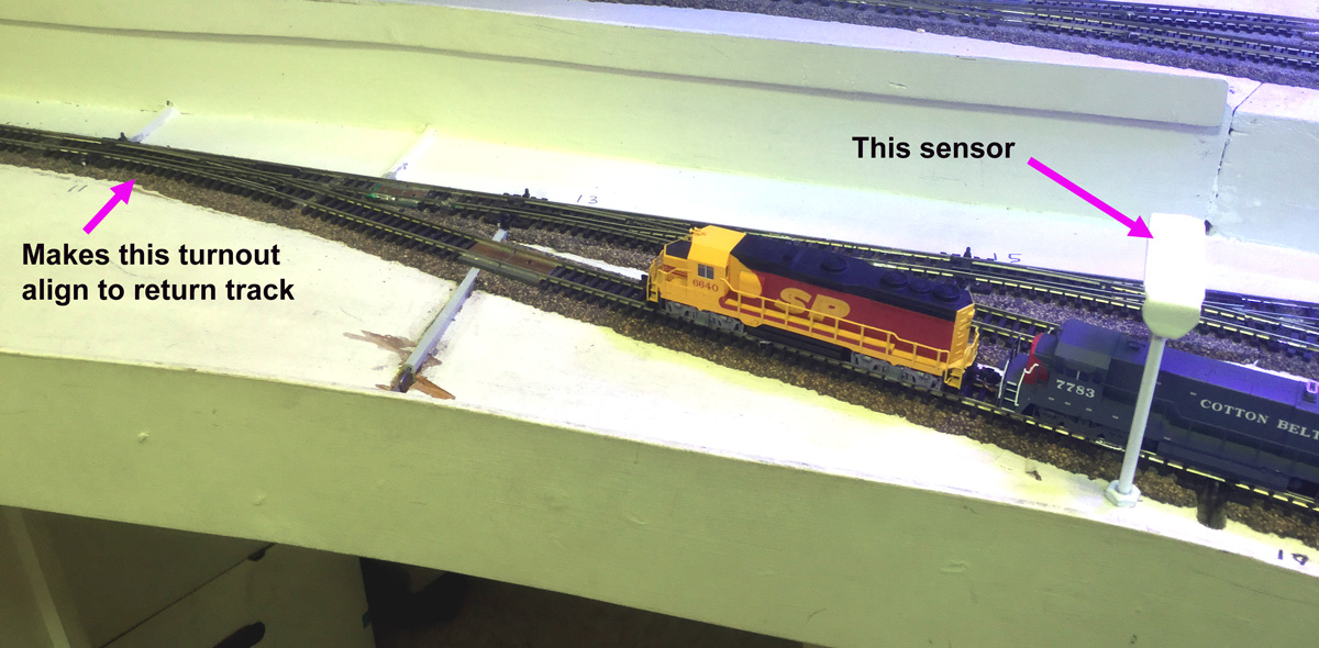
- Rebuilding of Sparks staging with new controls and automation
- Added interior detail and lights to the warehouse in Battle Mountain
- Installed new low profile wheels on 14 old Kato locomotives
- Added some track powered tail lights to the Amtrak California Zephyr
- Discovered a new product to clean track and wheels
- Finished a Showcase Miniatures MoW truck
This winter I am again participating in the annual Trainboard.com Winter Layout Party. I have noticed that there seems to be more people participating this year so I must not be the only one spending more time with their layout.
Already the N Scale convention in Sparks, Nevada that was scheduled for next June has been canceled and I suspect that it is going to still be some time before it will be safe to travel or have train shows again. Until then, I'll just keep working on my railroad.
Happy New Year !