Showing posts with label helix. Show all posts

Saturday, June 27, 2026

Signaling for the Lovelock section

The Lovelock section of the layout is connected to the main line by a turnout at the bottom of the helix.  The helix already has signaling controlled by an occupancy detection circuit.  I want the new signal and both of the existing signals to monitor the position of the turnout as well as occupancy of the helix.

To accomplish this I used a diode matrix type of technique.  Refer to the drawing below.  The two diodes that are in parallel with the relay coils are just there to suppress back EMF when the relay opens and don't affect the logic of this circuit.  The two diodes that are on the input from the detection circuit isolate the two relays from each other and prevent the 12 volts from the tortoise contacts from reaching the relay 

The use of a Peco insulfrog turnout at the bottom of the helix means there is no frog to route power to.  This left both sets of contacts on the Tortosie switch machine available to control the signals.  Referring to the photo below, +12 volts DC was connected to both commons (red wires).  The orange wires are connected to the position contacts.


This is the new circuit board to control the new signal.  The red and black wires are 12 power, the orange wire is from the Tortoise motor contacts, and the yellow wire is from the occupancy detection circuit.  The red and green wires are the outputs to the signal.  Notice the diode on the board between the terminals where the orange and yellow wires are terminated.  This diode allows the occupancy signal on the yellow wire to activate the relay but blocks the turnout signal from affecting the relay on the board for the helix signals.


At the board that was already installed to control the signals at the top and bottom of the helix, the diode was placed in line on the wire that connects it to the detection circuit.  This diode will prevent the signal from the orange wire on this board from affecting the relay on the new board.


So here's the new signal on the Lovelock siding.  It will indicate a red whenever the helix block is occupied OR the turnout is aligned to the staging yard.


And here is the same signal showing a green when the turnout is aligned to the lovelock siding AND the helix block is clear.


Thursday, November 21, 2024

Expanding the signaling, again.

Over the past few weeks I have been working on the signaling on the layout.  First to correct some problems I've had in one of the signal blocks, and then to expand the signaling to the upper helix. The signaling on this layout is just red / green aspects with the actual signals being something I have scratch built myself.  Below are links to some of the earlier posts I have made on the signaling.

July 2021 - Expanding the signaling

July 2020 - My home made searchlight signals

May 2020 - First working signals on the layout

So the first step was to correct a problem I have been having with sensitivity on the Southern Pacific line in the 3rd signal block which includes the Carlin yard.  The NCE detectors I have been using don't have any sensitivity adjustment so I picked up a circuit from Azatrax that does have a sensitivity adjustment to see if that would make a difference.  After installing it, I was able to adjust it to get the results I wanted.  A nice thing about this Azatrax circuit was that the double pole relays were included on the board so I did not have to make up a relay board like I have been doing for the NCE sensors.


The sensors and relay board that had been removed from the 3rd signal block location was installed to provide detection for the upper helix which has become the 4th signal block.  They works fine there, I think because the track arrangement is simpler.

At the top of the upper helix the occupancy for each track is indicated with bi-color LED's that were added to the upper return loop control panel.

At the bottom of the upper helix near the east end of the Carlin yard, a pair of signals indicate the occupancy within the helix.


At the west end of the Carlin yard where the crossover leads to the WP track, another signal is connected to the WP signal block.  In the future I would like to have the signal only be green if the block is clear and the turnout is aligned for the crossover.


Tuesday, December 20, 2022

Winter 2022 layout construction update

We got our coldest weather a bit early this year with it getting into the 30's since Thanksgiving.  So I've been running the little heater and spending quite a bit of time in the train room and getting a lot done at the eastern end of the layout.

As mentioned in the previous post, the completion of the east end return loop means that the entire main line is now done.  This first photo shows the return loop with the pair of stub end staging tracks in the middle.  This area is directly above the Weso section of the layout and is at 68 inches from the floor.  This happens to be my height and I can easily reach this with a short step stool.  Trains that come into those stub end staging tracks will need to have there engines and caboose swapped by hand.


This next photo shows the entry into this area which is at the top of the helix.  The arrangement of the turnouts allows for a train to enter or leave the staging tracks from either helix track.  In practice they will mostly enter from the eastbound WP/UP line and depart from the westbound SP line.  I had a box of used Peco turnouts that had been given to me years ago and selected 4 that appeared to be in the best condition.  So far they are working well but all of these are just track nailed down so future repair or replacement is possible if any problems occur.


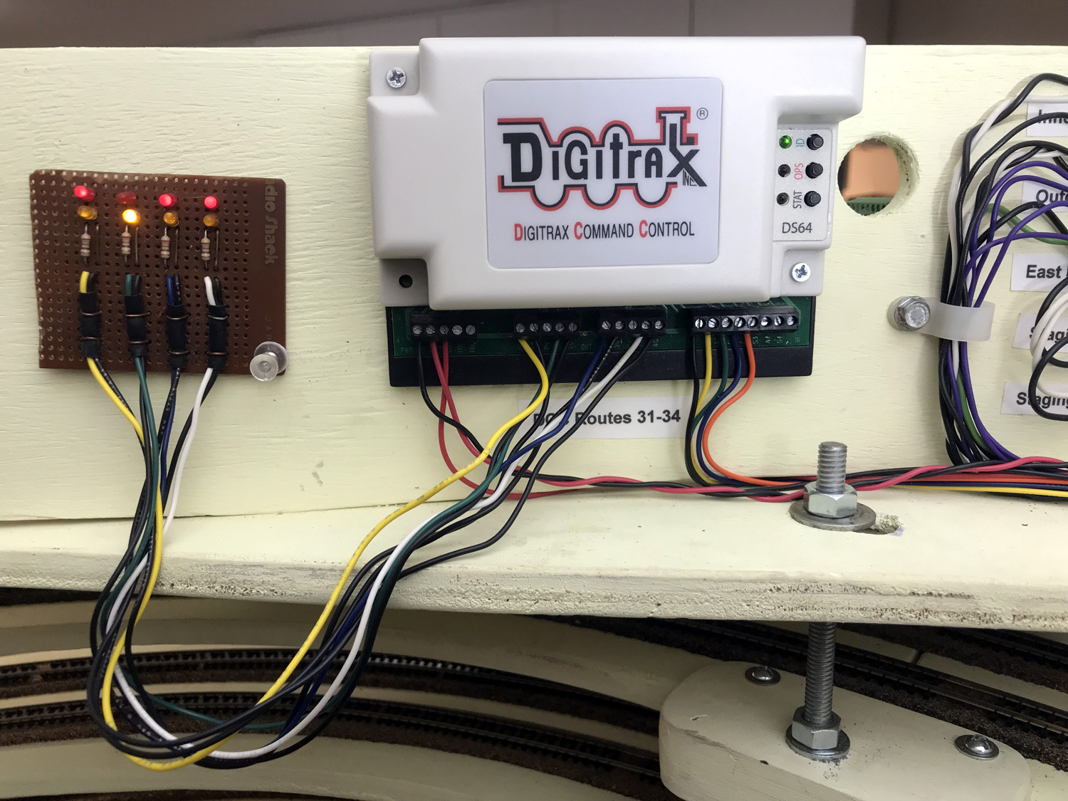
The short wall that is visible behind the Tortoise motors is to allow mounting of circuits and connections related to this area.  In this next photo some of this is visible including the Digitrax DS64 that controls the turnout motors.  Wiring is still in progress at this point.  The circuit board shown connected to the DS64 outputs is a test board I made up to assist with programming.  The Yellow LED's indicate a closed turnout position and the red ones indicate a thrown position. 


For now at least this group of turnouts will be controlled by this control panel which is currently mounted on a scrap of hard board which is attached to the helix.  Eventually the fascia will be extended from the left and this panel will be mounted to that.


Again this winter I am posting in the Trainboard.com annual winter layout party thread.  There have not been any train shows again this year for me to exhibit my Ntrak modules or AsiaNrail modules.  Two events are scheduled next year in April and June but until then I'll just keep working on this layout.

Monday, January 30, 2017

First trains reach Wesso from the staging yard

With all the track connected from the staging yards through the helix and the Wesso sections of the layout, it was time to run some test trains trains.  There is a limited amount of track east of Wesso junction but short trains can be run through the cross overs and return on a different line than they went up on.

A pair of UP GP40's will start from the upper staging yard and a pair of SP SD35's will start from the lower staging yard.  Each pair of locos has an Aztec track cleaning car in between them.

The SP train goes out first.

After climbing the helix the SP train arrives at Wesso and takes the cross overs from the SP line to the east bound paired track.


The UP train leaves next, starting it's climb up the helix.  Because the upper level staging yard is one helix turn higher than the lower yard, this line has a one turn shorter run in the helix.

The UP train leaves the helix, passes through the  small Winnemucca section which does not have scenery yet and approaches Wesso junction.

The UP train takes the cross over from the WP / UP line to the west bound paired track.

After passing through the cross overs, both trains arrive at the end of line both in terms of track and scenery just past the dry creek area.  The UP train on the west bound track and the SP train on the east bound track.

After all of the points of the cross overs have been aligned, both trains begin moving west bound to return to the staging level.  This time the UP train is entering the SP track to the lower level and the SP train is on the WP / UP track to the upper level.

On the trip down to the staging yard the UP train has the smaller radius and moves ahead of the SP train.  The SP train however will leave the helix one turn before the UP train so they both end up in the staging yard at about the same time.

Here we are back at staging with the trains in opposite yards from where they started.

For the first time there is a connection between the two staging yards although it still requires a reverse move in one direction.

Sunday, January 22, 2017

Connecting M/E code 55 to Atlas code 80 track

The Wesso section has been bolted into place and the cork road bed installed on both line connecting the road bed between the helix and the Wesso section and it was time to make the track connections. The Atlas code 80 track from the helix would need to be connected to the Micro Engineering code 55 on the visible parts of the layout.  There would also need to be a gap in the rails at the point were the helix and main line DCC power districts meet.

This was the first time I had connected Atlas code 80 track to Micro Engineering code 55 track.  I started by making a plate from PC board material as I had done for track gaps in the staging yard, but this time I added a pair of .020 thick brass strips on one end.

The brass strips brought the code 55 rail up to the height of the code 80 rail.  Then it was just a matter of aligning and soldering in place on the plate.

It is not pretty but it works.  These will be out of view behind the sky board near the helix.

The isolation gaps between DCC power districts on both lines will be in the visible areas of the layout on the code 55 track.   For that I am using a product called Gapmaster from the American Tie and Timber Company.  These are 4 tie sections made from PC board material with a gap in the middle of each tie.

In the case of the WP line shown in this photo, I had two sections of M/E code 55 track where I used the Gapmaster instead of rail joiners. Then just a couple of passes with my razor saw to remove the PC board plating and complete the gap.

On the SP line I removed 4 ties and replaced them with the Gapmaster, then sawed through the rails.

I had already used the Gapmaster with very good results on the double crossovers at Wesso.

This photo shows one of those after the track was painted and ballast was applied.  After the ties are painted they blend in with the rest of the ties.

Wednesday, February 17, 2016

Lower helix conclusion

1/8 inch hard board was used to wrap around the outer parts of the helix.  This will eventually be painted to blend in with the walls of the room.

Another piece of old 2 x 2 Ntrak module leg was installed on the outer edge of the "Winnemucca" section on the top,  this is grey in the photo.

In last October's Helix Progress post I had mentioned that there seemed to be a bit of a twist occurring in the helix sections causing there to be a slight difference in the spacing in some places.  I was able to solve this by making 4 spacing strips that hold the outer edge at a spacing the 2-/14 inches between levels.  One of these was mounted on the outer edge between each all thread rod.

Each loop of the helix has a pair of 22 gauge feeder wires which are connected to a 2 position terminal strip.  Then that terminal strip is connected to the output of a PSX-1 under the helix.

This photo shows the connections for the inner or WP tracks.  The connections for the outer or SP tracks are on the opposite side of the helix.


While this marks the completion of this lower helix, there will eventually be another helix stacked on top of this one that will connect the other end of the layout to a return loop and siding that will be above Wesso after the layout goes all the way around the room.

Sunday, December 27, 2015

New territory for the new year

After 5 turns and 14.5 inches of climbing from the lower section of the staging yard the helix is nearing completion.  The last section for the helix is a special transition section that will connect it to the Wesso section.  In this section the Atlas code 80 track will be connected to the Micro Engineering code 55 track and part of it will have scenery representing the edge of Winnemucca, Nevada so this small section will be referred to as the Winnemucca section.

To cut out this section I first made a cardboard template.  Once I was satisfied with the fit of the template I traced it's shape onto a sheet of plywood and cut this out with a saber saw.  There were still some minor adjustments to be made to get the fit just right.

To install this section it had to be put in over the all thread rods, then slide the end into the last pair of splicing blocks.  To do this I made slots for the rods instead of holes as seen in this photo.

Besides being supported by the rods and the helix splicing blocks there is also a 3/4 inch ledger along the wall where that end of the section is secured.
This end of this small section of bench work will connect to the Wesso section which I have already started to cut the parts for and will post on soon.  The holes shown in this photo are to accommodate any wiring between the two sections.


So as 2015 ends and the new year begins the layout is enter a new and exciting phase.  The most complicated bench work for the layout is now complete and section by section it can now progress around the train room.

Thank you everyone who has been following my slow progress on this layout. May you all have a safe and happy 2016.

Friday, November 6, 2015

The work train

After cleaning up the area around the helix which had gotten rather messy I am determined to be more organized in my work.

I decided to have some fun with it and made up a work train of gondolas and flat cars to bring some of  track laying materials and tools to within my reach then send it back down to the safety of the yard.


Work on the helix is moving along with a repeating  pattern of adding a section or two to the structure, then adding cork roadbed, and then the track.  Getting close to the height it needs to be.

Saturday, October 31, 2015

Helix progress


Work has been progressing on the helix.  This photo shows the helix as it currently is.  Both yards are tied in now with the outer loop from the upper yard climbing a little more than one turn and the inner loop from the lower yard climbing two full turns.

The inner loop from the lower yard and the outer loop from the upper yard each have there own power district.  Each turn of each loop will have a feeder.

I picked up a roll of 16 gauge paired wire from Powerwerx.com to use as the main bus that will connect the inputs of all the PSX modules in the layout to the DCC system.  That is the black and red wire shown in this photo.  The outputs from the PSX power district modules are 18 gauge.


One of the reasons I am using the threaded rod design is to have the ability to experiment with the performance of equipment in pulling a given train up the grades and make adjustments if needed.  The last layout had 4 % grades which worked fine but those were short and the trains I ran on that layout were normally only 8 or 9 cars long.  I knew the grade would have to be less than that on the helix.

I started out with a rise between turns on the helix of 3 inches.  This calculated out to being 2.5 % on the outer loop and 2.8 % on the inner loop.  Then I began to run trains up the helix with various types of cars and locomotive.  I plan to run locomotives in pairs on most trains and most of the sidings will hold about 20 or so fifty foot cars.  With the 3 inch rise the 6 axle units did fine but the 4 axle units would start to loose traction about the time the full train was on the grade.  So I began to adjust the levels of the helix downward.

What I settled on was 2 - 3/4 inches between the levels.  That 1/4 inch seem to make a big difference.  Both 4 and 6 axle pairs of  locomotives can now pull trains longer than the staging sidings up the helix.  With 1/2 inch thickness of the decks, there is 2 - 1/4 inch of clearance which is plenty for the highest cars and my small hands still easily reach between for cleaning track for re-railing a car.  So far, with all my testing not a single car or loco has derailed within the helix.  So the final grade on the helix is going to be 2.3 % on the outer loop and 2.5 % on the inner loop.

Once I decided on the space between levels, I cut a piece of scrap material to use as a height gauge.  Adding the 1/2 inch thickness of the plywood structure to the 2-1/4 inch space make each turn lift 2 - 3/4 inches.


Another tool I made was a double ended guide with a stop that rest at the inner edge of the deck and lengths for the inner and outer loops.  Once the lines are drawn, the installation of the cork road bed and track goes easily, two sections for half a loop at a time.


I have noticed that the helix sections seem to have a little twist in them after being installed which makes the spacing vary a bit between some levels.  While this does not seem to affect the operation in any way I would still like to keep the spacing consistent so I may add some thin spacers between the threaded rods.

Monday, October 12, 2015

1 year since construction started

It's been just about one year since construction started on the layout.  Here's what got done on the layout in that one year.

  • Staging yard bench work built, track laid, wiring done, and yard installed.
  • 15 feet of LED layout lighting installed.
  • Yard control panels started and one completed.
  • Started the helix.

Today I built the little bridge section seen in this photo that connects the upper level staging yard to the outer loop of the helix.  This section will support the turnout that creates the reverse loop for the upper yard.  Helix progress has been stalled until this is done.  It will be the last of 16 code 80 turnouts associated with the staging yards.

The helix design has been working out really well so far.  The lower level yard is fully installed and various types of trains that been run up and down the helix to iron things out.  Turnouts on the lower yard have to be moved by hand as the control system for that part is not done yet.

So what will I accomplish during the second year ?  Well, I'm looking forward to finishing the helix and building the bench work Wesso Junction and Carlin sections.  I'm also looking forward to working with the code 55 track that will be used after the helix is done and of course starting some scenery.

Monday, September 21, 2015

Helix assembly begins

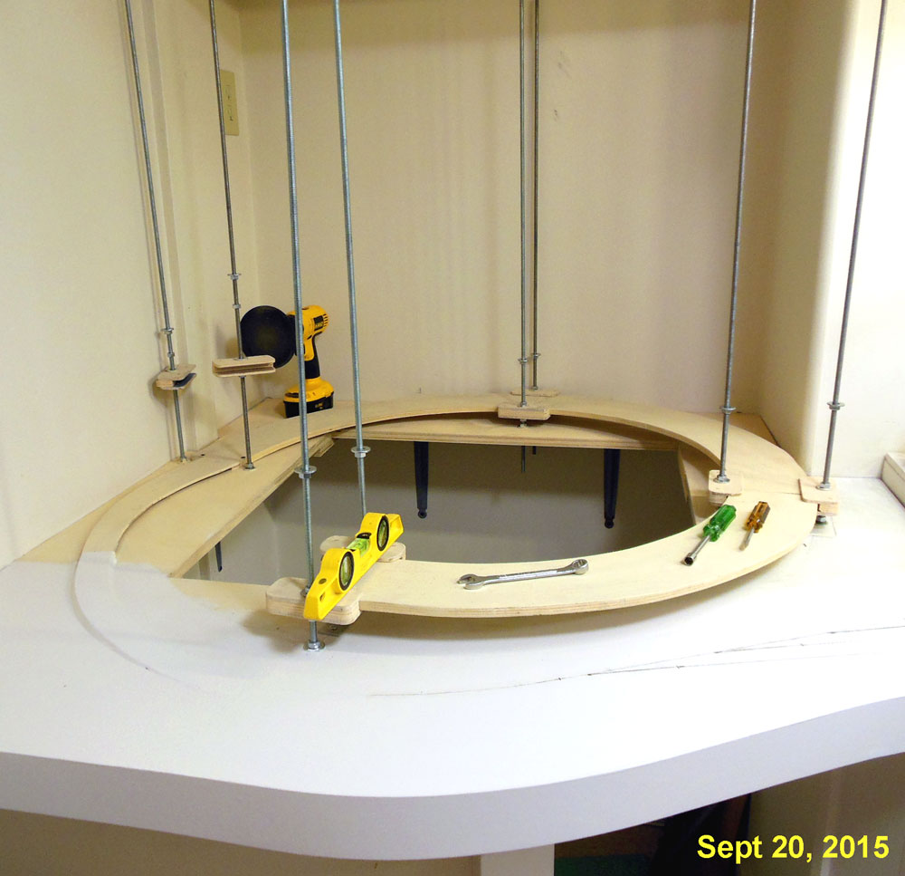
The 8 threaded rods and the first few sections of the helix are now in place and ready for cork roadbed.  The track from the lower yard will enter the helix from the bottom and the track from the upper yard will enter after 1 turn, about where that wrench is in this photo.

To create a smooth transition for the track from the lower yard to start the climb I used my router to carve out a 1/4 inch depression in the 3/4 inch base then glued and stapled a 1/4 inch plywood sub road bed in place.  This will gently start the climb up from the flat surface.

That first single track section of sub road bed meets another 1/4 inch thick sub road bed section that completes the first 1/2 inch of climb and meets the first true helix section.  It also flares out from single track width to double track width.

One of the more tedious parts of using the threaded rod helix design is threading all those nuts onto the rods.  After trying several ideas to make this go easier and faster, I settled on using the attachment for a disk sander without the sand paper.   The rubber backing has enough grip to move the nut around.  This works in both directions by reversing the rotation of the drill motor.
Monday, September 7, 2015

Base for the helix

For the Labor Day weekend our local hardware chain was running a "We pay the sales tax event" so I loaded up on some of the supplies to further the layout construction and that motivated me to get started on the helix.  I had already prepared some helix sections but needed to prepare the base that the helix would be mounted on.

The short wall in the corner was already in place from the construction of the layout room and what was needed was a platform on top to mount the all thread rods to.  That platform was made of 3/4 inch plywood.

4 of the helix sections were temporarily assembled into a loop to get an idea of where the rods would be.

The parts of the platform that were not going to be on top of the short wall are supported by shelf brackets.

This small space will allow access to the inside of the helix.  Notice the AC outlet and LP air nipple on the wall, this is also where the compressor is housed but can be easily rolled out of the way when necessary.

Also a few pieces of 3/4 inch plywood were used to tie in the yard to the platform that the helix will sit on.

Next I'll be continuing the tempered hardboard fascia that is on the yard section to this section.

Thursday, June 18, 2015

Helix design

When I decided that I would need a helix to do what I wanted to do on this layout I studied everything I could on the Internet and examined first hand any helix that I could.  The room that I built in the back of my garage is a 20 x 10 ft rectangle but has a 2 ft bump out in one corner for part of the helix.  The net space set aside for the helix is 42 x 42 inches.

I really liked the idea of using all thread rods to support the helix because it would allow me to experiment with some different grade adjustments plus it offered the best access to the tracks.

My design uses 90 degree curved sections of 1/2 inch plywood that are 4.5 inches wides.  The radius on the outer edge of the curved sections is 20.5 inches.  Between each section a pair of splicing blocks hold the sections together and attach to 3/8 inch all thread rod.  Two 8-32 screws on each side of each section will secure the splice blocks to the curved sections.

I found that I could get 10 of the curved sections from a 4 x 4 sheet of birch plywood.  After making the first one I marked it as master and used it as a template to draw the others.


The splicing blocks are made from scraps of the sheet that the curved sections were cut from in between 1/4 inch thick birch plywood material.  The overall size of these assemblies is 4 inches x 2 inches.

Here are the results from a single 4 x 4 sheet of plywood.  The curved sections on the left have been painted. All sections will be painted prior to assembly.  This is a start, my plan is by doing some of this now, I'll be able to go right into assembling the helix after the yard is completed and installed.