Showing posts with label Azatrax. Show all posts

Monday, June 24, 2024

Summer 2024 layout update

We are already almost half way through 2024 and June 20th marked the first day of summer this year so here's a summer layout update.

I have been working on finishing the occupancy indicators for the east end staging and return loop.  Going to be using the last 2 of the 8 channels of the Azatrax MRD8 unit that I never thought I would fill.  With a total of 32 input wires and the small spring type connectors used on the board, I have found it difficult to get a reliable connection for the last few inputs especially when more than 1 wire has to connect to a terminal.  So I have installed a 25 screw terminal strip to make it easier.


I needed some more Azatrax IR sensor pairs for that project and when ordering them I noticed the Azatrax also has a dual track occupancy detectors so I ordered that as well as I am also going to be adding signaling to the upper helix.  I noticed that these have a sensitivity adjustment on the board and am looking forward to seeing how that works.  I'll post more detail on both of these projects as they develop.


And I have been working on finishing another 3D printed house for Carlin.  All three of the houses got a primer coat at the same time last year. This one, the 2nd one recemt;u got a base coat of white and I am now working on hand painting the details.


Wednesday, November 23, 2022

Update to the yard sequencer

About 2 years ago I added some automation to the Southern Pacific staging yard using some Azatrax IR detection modules. The idea was to have a train enter the yard and stop on one a particular track and another train automatically leave on another track.   The post I made on this in November 2020 is HERE.

This has worked well but occasionally when after coasting to a stop the space between 2 locomotives lands right over the receiver that is under the track.  These particular Azatrax units close a relay contact momentarily but will continue to show detection as long as the beam is blocked.  When the beam is no longer blocked, the circuit is reset.  When it is time for the train to go out again, as soon as it moves the beam is blocked by the second locomotive and the circuit thinks the train has just arrived and switches to the next train in the sequence. 


After giving this problem some thought over a period of time I came up with some ideas on how to overcome this and recently I put those ideas to the test.  First I removed the IR transmitter stand and carefully bent both the 1/8 inch rod and the 1/8 inch tube near where they go through the deck.  This would hopefully prevent the beam from passing through between the locomotives.  After re-installing them I re-tested by slowly pushing a pair of flat cars over the IR receiver.  This helps as but did not totally correct the problem.  Next I pushed the IR receiver down deeper into it's hole between the ties.  This again was an improvement but did not totally prevent the beam from passing through to receiver.  Last, I made a lens from .250 wide by .010 Evergreen strip with a hole of about 1/16 inch.  The hole was aligned over the spot where the receiver is.  This seemed to do the trick.


To test the arrangement I was using a Kato SD40-2 and an SD40 set back to back and slowly pushed them across the path of the sensor.  These have the most open back porch and when running back to back provide the largest path for the IR signal to get through.


While these adjustments seem to have corrected this issue, the real test will come when the upper helix and return loop are finished.  Then I can setup several trains to run in continuous operation.

Tuesday, August 2, 2022

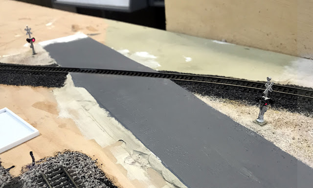
Grade crossing in Carlin

In the real Carlin, there are a pair of multi track grade crossings, one at 4th street and another at 10th street.  I wanted to keep my small modeled yard clear of any grade crossings but did find a spot where Main street crosses the Western Pacific line to include one of these interesting features.

The grade crossing that I had set up in Battle Mountain a few years ago was no longer working correctly but the signals themselves were OK so I transplanted them to Carlin.  These NJ International signals have lights on both sides and as this crossing would be visible from both sides I wanted to use them here.  When I rebuild the crossing at Battle Mountain I plan to scratch build some signals that will only have lights on one side as they can only be seen from the front.   In Carlin I am using the crossing controller from Azatrax with the IR transmitter and receiver being in between the ties using the reflective mode.  For the sound I am using the ITT Products grade crossing module.  These circuits are mounted under the bench work.


The instructions that same with the sound module recommends a speaker with an 8 ohm input impedance.  For about $5.00 each on Amazon I found some 2 inch, 8 ohm speakers.  I am impressed with the sound quality from these.


These speakers are also small enough to hide in a small structure.  This one will be in a 3D printed house that is nearby the crossing.  I still need to get the part between the rails done and also some markings on the road.


When I set up this signal, this section of bench work was still on the saw horses and everything worked great.  After installing the section into the layout the sensors started to get false triggers.  What was happening was that the invisible IR beam was reflecting off the bottom of the cabinets which are 17 inches above the track.  I taped up some of the same black craft foam that I used on the roads and that seems to have solved the problem.  So I may need to either attached these foam sheets more permanently or paint the bottoms of the cabinets a flat black in this area.

Saturday, November 14, 2020

Yard sequencer

In previous posts I had mentioned the use of some automation in the staging yard, here is just a bit more detail about how that works.

I am using Aztrax IR sensors to sense when a train arrives on one of the four staging tracks.  The sending units are in stands made from brass while the receiving units are in the tracks between the ties.  These are positioned near the departing end of each staging track.

The post on one side of the stand is 1/8 inch hallow tube and the wires for the IR sending unit are fed down through it.  The post on the other side is 1/8 inch rod that has had the end threaded for 6-32 sized nut.  Before the IR sender LED's were installed, the stands were spray painted white.  After the IR sender LED's were installed white heat shrink tubing is slipped over after a hole is punched on one side for the sender.


Referring to the control panel photo and diagram below I will attempt to explain how this works.  When a train arrives at the IR sensor pair it triggers a one second closure of the relay on the Azatrax board. The relay contact outputs of the Azatrax units are wired in parallel with the push buttons on the control panel associated with the next track but first pass through a toggle switch labeled Auto / Manual in the photo.  In the auto position the contact will trigger the turnouts for the next track and the train on that track will leave.  In the Manual position that track will be skipped and the closure will go to the next track.   This allows the flexibility to use any of the tracks and skip others in the case there is no train on that track. 


In the photo below one of those IR sensors between the ties is pointed out.  This system has been working out fairly well.  I did have to move the sensors around a bit to allow for the arriving train to coast to a stop before reaching the end of the siding.   Also it does occasionally happen that the train stops with the sensors being right between the first and second locomotive.   If this happens then when that train goes out again, the second locomotive will be mistaken as an arriving train and cause the sequence to move to the next track.


Monday, June 15, 2020

More experiments with Azatrax

Lately I have been finding more ways to use the Azatrax Infrared (IR) train detection circuits and sensors. Recently I received a pair of single channel detector circuits that operate a bit differently than the 8 channel circuit that I featured in the posts Experimenting with Infrared detection circuits and Automation of the yard's reverse loops.

This is the MRD1-V.  The V in the model number is for variable delay.  When the timing adjustment is turned all the way counter clockwise,  the relay will turn on for 1 second then turn off even if the beam is still blocked.  This is called one-shot operation.
The one shot operation is like pressing a momentary button on the control panel.  By connecting the relay in parallel with a panel button this could allow for some automation of the staging yard.  I built a small brass structure to mount an IR transmitter on top looking down with the receiver in the track.  The actual IR beam is invisible but the green line indicates where it would be.
The 1-1/2 inch spacing of my yard tracks is enough for the the trains to clear the 1/8 inch poles of the structure.

So with the relay output connected in parallel with one of the push buttons on the control panel this concept was successfully tested by pushing various cars through the structure.


Here is the MRD1-V temporarily sitting under the staging yard with the beam blocked indicating occupancy.  There is an occupancy LED on the board plus connections to have a panel mounted occupancy LED if desired.
I also tried out the reflective mode with the IR transmitter and receiver mounted through an old section of Kato track.   This also worked quite well with several different cars and locomotives but passing a hand over the sensors also could trigger the circuit so I will be careful where I use this setup on the layout.

Wednesday, April 1, 2020

Automation of the yards reverse loops

I have always been interested in making some things happen automatically on a layout.  This layout is giving me a chance to try out some automation ideas and this is the first one of these ideas that I have actually gotten to work on.

With this layout design it was not really possible to run a train totally hands free.  Which ever yard a train came into the turnouts that create the reverse loop would have to we moved to the correct position and then moved again for the train to leave.    The PSX-AR boards already take care of the track polarity but I wanted to automate the operation of the points on the reverse loops turnouts.

This diagram shows how I am doing this on each of the two yards using a combination of the detection sensors shown in the last post and IR sensors.
For the lower yard I cut a gap in one of the rails on the return track and then added an extra feeder wire that was fed through one of the detector coils before being connected to the track bus.
For the upper yard I am using the removable bridge on the return track as the point to trigger the reverse loop turnout to move to the diverging position.  It is already isolated with it's own feeder wires and one of those was fed through the other detector coil.


One feeder wire from each of track sections described above is fed through one of the coils on the detector board.

The detector assembly is mounted under the yard about where the the UP locomotive is in the previous photo.  This location is close to the feeder wires used for detection.


To trigger the reverse loop turnouts to move to the aligned position for trains entering the yards each line as an IR transmitter / receiver pair mounted on a wood frame at the top of the helix.  I was considering using the occupancy output from the helix PSX boards but that would cause the turnouts to change while part of a train is still crossing them.

This is the Azatrax IR control board that is located in the wall cabinet under the yard.

The normally open outputs from this board and the dual detector assembly are connected in parallel with push buttons on the control panel to set the turnouts in motion.
I have been running this circuit for many hours already while working on other project at the work bench and it works great.  Totally hands free with one train.  With more than one they may need to meet at the siding in Battle Mountain and that is done manually.

Thursday, January 11, 2018

My first Arduino project - a grade crossing

I have always wanted to create an automated grade crossing. Several years ago I had purchased a grade crossing bell sound module and a pair of NJ International crossing signals with LED signals.  I have experimented with these items a few times but never got around to actually incorporating them into a layout.

As mentioned in the last post for the past few years I have also been experimenting with Arduino micro-controllers.  It was time to bring everything together.  The road that connects a few industries in Battle Mountain to the rest of the world seemed like a good place to finally create a nice crossing scene.

It was a bit of work but I have the results I was looking for, an automatic grade crossing signal with flashing lights and bell sound.  Work remains to be done to finish the scene but this photo shows it working.


It took all this hardware under the layout to make this grade crossing happen.  Probably not the most efficient setup but it works.


Infrared sensor pairs are hidden in the scenery on either side of the grade crossing.  In this photo looking up from a low angle one of the receivers can be seen inside a cave in one of the rock outcroppings.  At a normal viewing angle this is hardly noticeable.

Transmitters are embedded into the scenery on the ground on the other side of the track and because they face away from the viewer they can't be seen at all.


And now for the tricky bits


Here is the complete schematic drawing of this project.    After almost 1 year with a new computer and learning new versions of software,  I think I am finally getting up to speed with the latest version of Microsoft Visio.


The code and some other notes:

This program is only using part of what the Arduino Nano can do and only using a small part of space available for program storage.

No gates on this crossing but they could be could be added if desired using left over outputs.  I have seen on the Internet where the analog outputs can be used to drive a servo but I have not tried this yet myself.

Arduino outputs are rated for 40ma.  There are a total of 8 LED's on the signals wired in pairs.  I measured the current flow on each pair of LED's at 6ma so two outputs could have done them all but since I had extra outputs I elected to use 4 outputs with each output running 1 pair of LED's.

Sound module runs continuously with connection to the speaker controlled by the relay.  One sound module could be used for multiple crossings with each crossing having it's own Arduino controlled relay module.  The sound module will drive a small 8 ohm speaker.
 

Approximate costs and sources:

  $5.00 - Relay module, ebay
  $6.00 - Arduino Nano, ebay
  $4.00 - Arduino Nano terminal adapter board, ebay
$89.95 - Azatrax MRD8 detector set,  Azatrax
$39.00 - Sound effects module, ITT Products
$35.00 - Crossing signals, NJ International

I had originally acquired the 8 channel Azatrax unit to work with staging yard automation and plan to replace it in this application with a pair of single channel units at $20.00 each and move the MRD8 to it's original purpose.  Azatrax also offers a unit specifically for grade crossings which might not require the use of an Arduino at all.

Now that the ice has been broken for me with the Arduino I hope to try out some other projects in the near future.

Thursday, January 4, 2018

Experimenting with Infrared detection circuits

Looking at some different options to trigger the grade crossing signals that I am planning for the Battle Mountain section and thought I would try an off the shelf product that uses pulsed Infrared or IR light.  IR light would have an advantage over normal photocells because it is less likely to be effected by room lighting and would work even in the dark.  I still have my "test layout" with Kato Unitrack which will be used to check things out before actually installing anything on the main layout.

For my experimenting I am using the Azatrax MR8D board.  Power for it can be from 8 to 16 volts AC or DC.  It can support up to 8 transmitter / receiver pairs and provide a solid state contact closure output for each of the 8 channels.  Each channel has an LED indicator which lights when something breaks the invisible IR beam between transmitter and receiver.
The set came with pairs of transmitters and receivers with leads attached and styrene tube protecting the connection.  The devices themselves look like 3mm LED's.

The Azatrax instructions recommended setting the devices at an angle across the track so the beam would not pass through the space between cars.  I used flat head screws and cut the styrene tubes into short lengths to hold the devices.  A 1/8 inch brass rod through both tubes holds the alignment until the adhesive sets.
I installed one set at a 3/4 inch height and another set at 1/2 inch height.  I then made up a test train with one each of several types of freight cars.

The 3/4 inch height worked OK except for empty flat or well cars.  As the instructions had suggested, there was no problem at all with the spaces between cars using the angled arrangement.
The pair set at a 1/2 inch height worked well for the 50 ft flat car that failed on the 3/4 inch height but was too low for the tank car.

Thinking about how the lateral angle was used to prevent the signal from passing between the cars, I thought that using vertical angle as well could help


So I lowered the transmitter screw on the pair that I had set at 3/4 inch to 1/4 inch.

This worked the best with very few instances of the signal getting around or through any of the cars in the test train.
Where my grade crossing is the track has low hills on one side with some exposed rock.  My plan is to embed the transmitter in the foreground scenery at ground level and the receiver in the hillside scenery at a higher level.

This photo with the IR beam path drawn in shows how the sensors could be installed on the  approaches to the grade crossing.


The Azatrax IR detection circuit seems to work very well and come in several configurations.  To learn about what is available check their website.