Showing posts with label electronics. Show all posts

Monday, August 4, 2025

Expanding sounds around the layout

I had received another Soundtraxx decoder and got it all installed as the sound for the road switcher in Carlin but was trouble programming it.  I would get a "No Ack" error message on the DT402 throttle I was using to program.

After viewing a YouTube video presented by George at Soundtraxx I learned that programming voltage is half of what track voltage is and that Soundtraxx decoders in particular are sensitive to this issue.  Soundtraxx had made a booster circuit for programming but it seemed to be out of stock and perhaps was no longer being made.

What I had not considered was how all this extra wiring running around the layout would degrade the programming signal so I decided to abandon the programming bus idea and instead use a jumper cord to program the sound decoders.  

I found these great 3D printed panel mounts for Power Pole connectors on ebay and installed them on the fascia next to each of the sound control panels.


A 1 inch diameter hole was drilled through the fascia next to each of the sound control panels.


The panel mounts fit neatly into the hole.  The wires from this connection are connected to the program position on the switch.


Then another connector replaced the existing Cinch Jones connector that my bench programming track plugs into and I made a long enough jumper cord to reach from the programming track output to anywhere on the layout.   The lead for the programming track also got it's Cinch Jones connector replaced.


Tuesday, July 8, 2025

Sound comes to Battle Mountain

Following the addition of locomotive sounds for the Carlin yard switcher, I have now added sound for the Lovelock local road switcher in Battle Mountain.

The Halliburton Barite processing building was the perfect place to install one of the 8 ohm, 3 watt speakers that I have been using on the layout.  It is in about the center of the Battle Mountain industrial district.


The decoder used was a Soundtraxx Econami designed for an HO Scale Atlas Diesel.  I glued an empty plastic prescription bottle under the bench work to hold the decoder in place.  The sound quality and volume from this decoder is quite impressive and it has more choices for programming to match the type of locomotive being modeled so I've been fine tuning those settings.


A control panel similar to the one in Carlin was created for this new decoder in Battle Mountain.   An additional decoder has been ordered and that one will be for road switcher sounds in Carlin where the speaker and control panel are already installed.


Thursday, November 21, 2024

Expanding the signaling, again.

Over the past few weeks I have been working on the signaling on the layout.  First to correct some problems I've had in one of the signal blocks, and then to expand the signaling to the upper helix. The signaling on this layout is just red / green aspects with the actual signals being something I have scratch built myself.  Below are links to some of the earlier posts I have made on the signaling.

July 2021 - Expanding the signaling

July 2020 - My home made searchlight signals

May 2020 - First working signals on the layout

So the first step was to correct a problem I have been having with sensitivity on the Southern Pacific line in the 3rd signal block which includes the Carlin yard.  The NCE detectors I have been using don't have any sensitivity adjustment so I picked up a circuit from Azatrax that does have a sensitivity adjustment to see if that would make a difference.  After installing it, I was able to adjust it to get the results I wanted.  A nice thing about this Azatrax circuit was that the double pole relays were included on the board so I did not have to make up a relay board like I have been doing for the NCE sensors.


The sensors and relay board that had been removed from the 3rd signal block location was installed to provide detection for the upper helix which has become the 4th signal block.  They works fine there, I think because the track arrangement is simpler.

At the top of the upper helix the occupancy for each track is indicated with bi-color LED's that were added to the upper return loop control panel.

At the bottom of the upper helix near the east end of the Carlin yard, a pair of signals indicate the occupancy within the helix.


At the west end of the Carlin yard where the crossover leads to the WP track, another signal is connected to the WP signal block.  In the future I would like to have the signal only be green if the block is clear and the turnout is aligned for the crossover.


Monday, June 24, 2024

Summer 2024 layout update

We are already almost half way through 2024 and June 20th marked the first day of summer this year so here's a summer layout update.

I have been working on finishing the occupancy indicators for the east end staging and return loop.  Going to be using the last 2 of the 8 channels of the Azatrax MRD8 unit that I never thought I would fill.  With a total of 32 input wires and the small spring type connectors used on the board, I have found it difficult to get a reliable connection for the last few inputs especially when more than 1 wire has to connect to a terminal.  So I have installed a 25 screw terminal strip to make it easier.


I needed some more Azatrax IR sensor pairs for that project and when ordering them I noticed the Azatrax also has a dual track occupancy detectors so I ordered that as well as I am also going to be adding signaling to the upper helix.  I noticed that these have a sensitivity adjustment on the board and am looking forward to seeing how that works.  I'll post more detail on both of these projects as they develop.


And I have been working on finishing another 3D printed house for Carlin.  All three of the houses got a primer coat at the same time last year. This one, the 2nd one recemt;u got a base coat of white and I am now working on hand painting the details.


Friday, May 17, 2024

The Overland Hotel

The building that hides the speaker for the Carlin yard switcher sound is now finished.  This was a Design Preservations Models - Hayes Hardware kit.  The building itself was not modified as it fit nicely into the space I had for it.  

The theme of this building is that of an older hotel which has seen it's better days pass when the interstate highway was built.  It has been refurbished and has had a large neon sign installed on the roof that can been seen from the interstate highway in the hope of attracting business.

I had recently purchased a 3D printed set of 180 roof top details and used 9 of those on the roof of this building.  The animated sign if from Miller Engineering with the support structure being scratch built from styrene.  


The electronics for the sign clip into a plastic cap from a prescription bottle which is glued under the roof of the building.  The power wires for this go down through a hole in the bench work and are connected to a voltage regulator from Miller Engineer specifically for these signs.  The wires for the speaker also go through the same hole.


Thursday, May 9, 2024

DCC Sound my way - Part 2

After doing a bunch of experimenting with DCC sound over several years I had decided that instead of installing sound decoders in my N scale locomotives I would use just a few as stationary sound decoders in choice locations addressed to the locomotive working in that area.

To start with, I wanted to have the sound for the yard switcher in Carlin yard.  One of the small speakers was placed inside of one of the buildings across the street from the yard about in the middle.  It was glued down to the base as shown here.


The building that will go here is a Design Preservation Models Hayes Hardware kit shown here half finished.  It will be a hotel when it's finished.  Look for a future post on that project. 


Because I sometimes change locomotives assigned to the Carlin yard, I would need to be able to program the sound decoder to an address matching the address of the locomotive.  I installed this control panel on the fascia which allows for this.  Thinking ahead, I also included control for the road switcher assigned to the Carlin yard as that will be a future step.  A cable for the programming output was run around the layout from the command station to this panel.


The Digitrax SFX0416 decoder is quite small and was placed within the bench work behind the control panel.  It is pointed out with a red arrow in the photo below.


Saturday, April 27, 2024

DCC sound my way - Part 1

While I have DCC decoders installed in nearly all my locomotives only 1 has a sound decoder.  It's this Atlas SD7 which has an early MRC sound decoder.  The frame was milled to be able to get the speaker in.  Something I really did not like was how with any brief interruption of pickup from the track, the sound would cut out then start up again, plus the sound quality was not very good with the tiny speaker.  So this loco ended up sitting on a siding with it's idling sound running.  


At some point the technology of electrical capacitors developed into what are called a "super capacitor" which has a large amount of capacitance in a small size.  Adding such circuits to a DCC sound decoder installation eliminates this problem of the sound cutting out but it's still a challenge in N scale to find room for decoder, a speaker, and a super capacitor circuit.

For my next attempt at DCC sound, I chose to build a sound car.  This was built around an Atlas covered hopper car and used a Soundtraxx decoder and a "keep alive" super capacitor circuit from Train Control Systems.   Here is a LINK to a short Youtube video demonstrating this project.  And here is another LINK to this project on my DCC blog.


I ran this sound car as the first car behind the power after programming it to the same DCC address as the locomotive consists.  Sometimes when switching cars at either Battle Mountain or Carlin, I would park this car on a siding and with the address again programmed to match the locomotive doing the switching. This car worked well in both of these applications but the sound quality still left something to be desired.  An unexpected take away from the experience with this sound car was that I realized I got the most enjoyment from the locomotive sound when I was doing switching.

When I installed the grade crossing signals in Carlin, I used an 8 ohm, 3 watt speaker that I found on Amazon for about $6.00 and was small enough to fit into a house that was next to the grade crossing.  Here is a LINK to the post I made on that project.  I really liked the sound quality from this speaker.


About the time I had bought the Soundtraxx decoder I had also purchased a Digitrax SFX0416 sound only decoder with the idea to build a sound dummy locomotive with a Kato SD40.  I never got around to this project but one day was wondering if this decoder could drive one of the 3 watt speakers and how that would sound.   The decoder was able to drive this speaker and sounded better than anything I've heard from a speaker in an N Scale locomotive.  So it was decided that I would use this sound decoder and this speaker as a stationary setup to add sound to the Carlin yard switcher.  The next post will cover the details of how I did that.

Saturday, April 20, 2024

Glitter Gulch moves to Carlin

Over 5 years ago I modeled a roadside casino in Winnemucca.  It was made from a kit bashed building kit and included a Miller Engineering animated sign.  Here is a photo from that post in February 2019.


Problem with that scene was that it is in an out of the way location and the sign was not very visible to operators and visitors to the layout.  My version of downtown Carlin is somewhat freelanced but based on some buildings that had been there at one time.  I decided that one building would be a casino and moved the sign to this new building.


The building is a Design Preservation Crestone Credit Union kit.  A hole was cut into the roof of the building and a scratch built rooftop structure was added for the electronics that run the sign.  The Miller Engineering sign was mounted on the front of the building over the center 2 second floor windows.


The sign's electronics were mounted to the inside of the roof of the rooftop structure.  The switch on the circuit board sticks out  of an opening on the back so is accessible to turn the sign on or off.


For now the ground floor is empty but the building and it's base are removable so in the future I plan to add lighting and details to the interior.


Monday, December 4, 2023

Tortoise motor noise problem

In a post earlier this year, I reported about a Digitrax DS64 that had inputs that were no longer working.  I had replaced the DS64 with a control circuit I built myself.  This was on my WP staging yard. Recently I have been having some issues with the circuit that controls the SP yard as well. 

Specifically, the turnout at the wye that creates the return loop would sometimes cause the turnouts that control the siding on the return track to switch.  As this wye turnout can be triggered by a train passing a sensor while the train is still passing through the siding turnouts, this would cause a derailment.


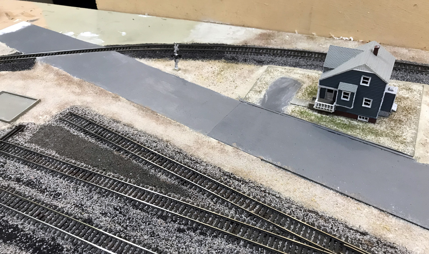
The turnouts on this staging yard are controlled by three different circuits as shown in this photo.  One controls the yard ladder, another the wye turnout and the third controls the siding turnouts.


I suspected that some sort of noise was getting onto the input connections of the board that controls the siding turnouts.  This was confirmed by monitoring the inputs with an oscilloscope. The inputs to the circuit are normally high at +12 volts and when the buttons are pressed or the IR sensor activated, they go low to 0 volts.   On the oscilloscope it could be seen that spikes were randomly occurring when the wye turnout motor was running and occasionally when the spike was large enough the inputs to the siding control board were being activated.


What was happening here was that arcing between the motor's commutator and brushes on the wye turnout were creating these spikes and the magnetic field from those spikes on the motor wires was being picked up by the input wires on the siding control circuit.    Notice in the photo of the circuits how many of the wires are bundled together.  This can contribute to this happening as can the age of the motors.  The Tortoise motors on this layout range in age from 9 to 30 years old.  When I built this staging yard 9 years ago I twisted the motor wires which is supposed to help eliminate this problem and it did for a long time.

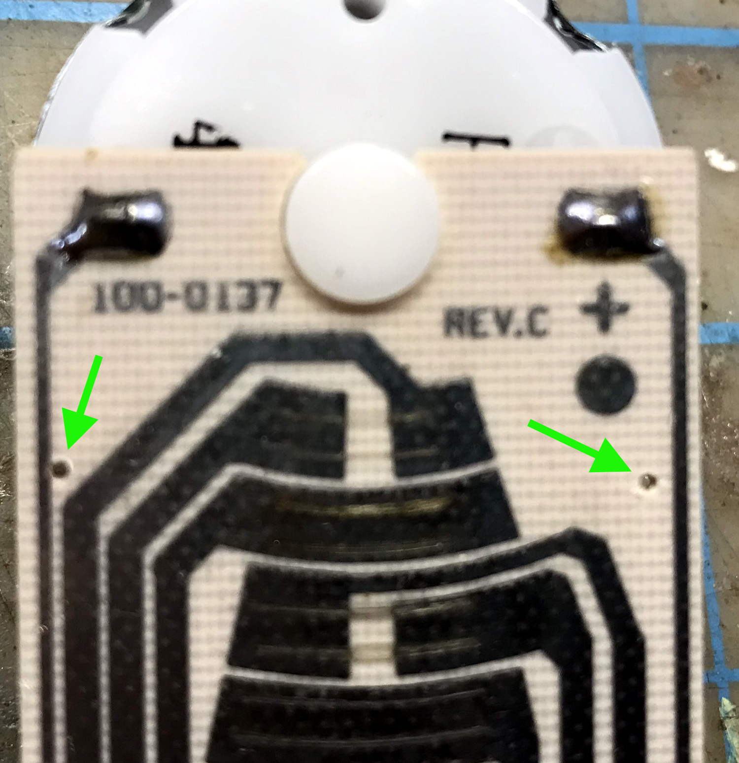
After reviewing several YouTube videos and some experimenting at the work bench I found the most effective solution was to suppress the noise as close to the source as possible.  I added a .01uf ceramic disc capacitor from each motor lead to the case of the motor.  After removing the motor from the Tortoise case, a pair of .039 holes were drilled in the circuit board at the locations pointed out with green arrows in the photo below.


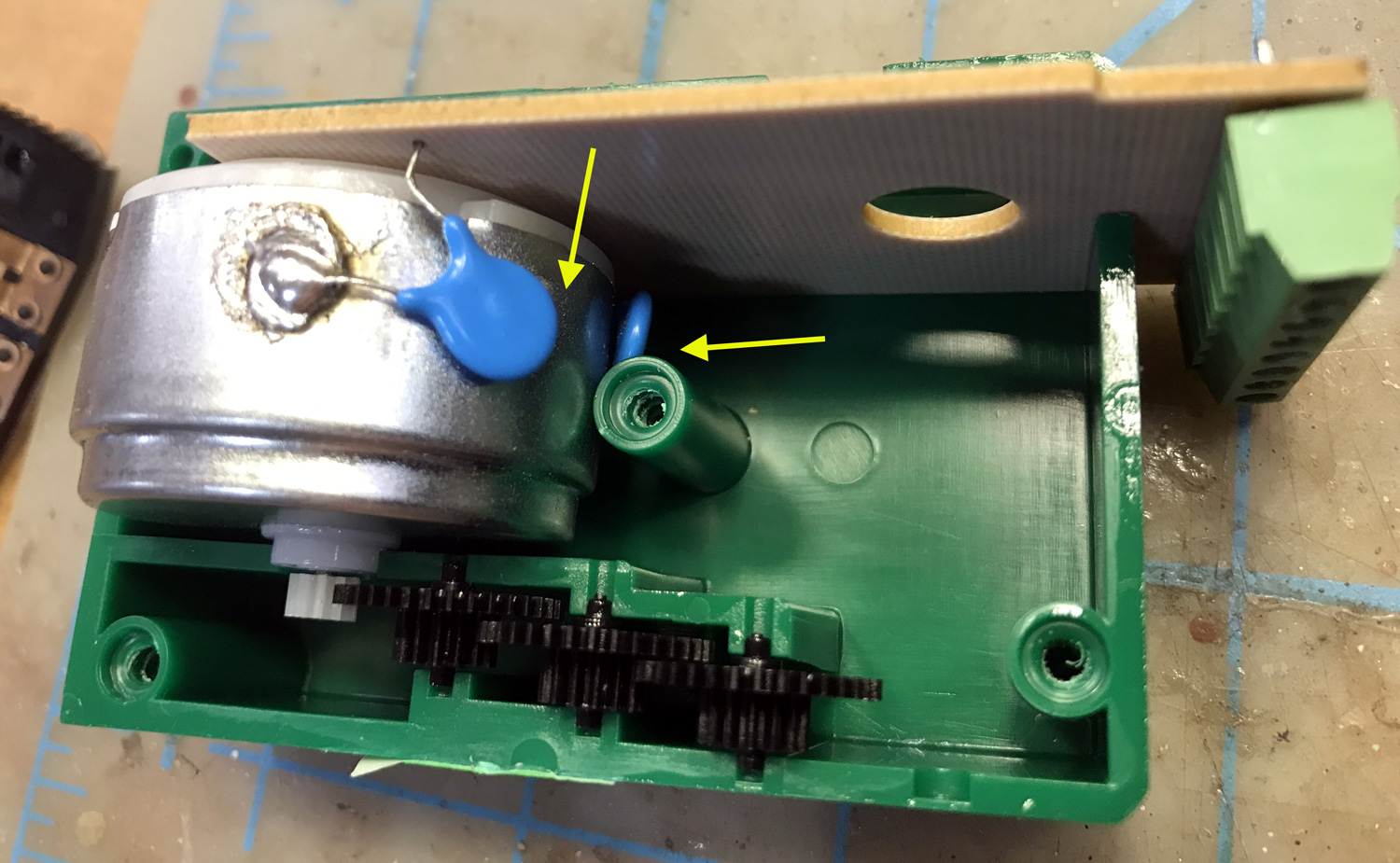
One lead of the capacitors were soldered to the case as shown in this photo.  To get a solder connection to the case I first scraped that spot on the case with a file and used flux and a hot soldering iron.  The other lead of the capacitors went through the holes in the board.


Then the leads that went through the holes in the circuit board were trimmed and soldered to the circuit traces as shown in this photo.


The placing of the capacitors this way prevents them from interfering with any of the moving parts inside the Tortoise housing and avoids the center screw mounts.


A recheck of the siding control inputs with the oscilloscope after the capacitors are installed shows a cleaner voltage with any spikes being very small.  After repeated testing, everything is working fine now.  I am now wondering if it was these voltage spikes that caused the inputs on the DS64 to fail.


Thursday, July 20, 2023

Changes for the Western Pacific staging yard

The west end Western Pacific staging yard had been in limited operation as being just a return loop since March.  I had replaced the wye control function of the non-operating DS64 with my own circuit but still could not use 3 of the 4 tracks.  Recently I built and installed the circuit to control the yard ladder.


With the new controls, the control panel also got some changes.  In the old scheme the track selected LEDs used a common return.  With this new scheme each LED is connected to its own track on both rails so additional connections were needed.  Removing the unused occupied LEDs freed up those connections in the control panel.

As I always run the trains in the same direction in the staging yard, I replaced the toggle switches which had controlled both the yard ladder and wye turnout with push buttons.  Then push buttons were added for independent control of the wye.  Those changes are pointed out in blue in the photo below.


So now this staging yard works the same way as the lower level staging yard but without the automatic function.

Wednesday, November 23, 2022

Update to the yard sequencer

About 2 years ago I added some automation to the Southern Pacific staging yard using some Azatrax IR detection modules. The idea was to have a train enter the yard and stop on one a particular track and another train automatically leave on another track.   The post I made on this in November 2020 is HERE.

This has worked well but occasionally when after coasting to a stop the space between 2 locomotives lands right over the receiver that is under the track.  These particular Azatrax units close a relay contact momentarily but will continue to show detection as long as the beam is blocked.  When the beam is no longer blocked, the circuit is reset.  When it is time for the train to go out again, as soon as it moves the beam is blocked by the second locomotive and the circuit thinks the train has just arrived and switches to the next train in the sequence. 


After giving this problem some thought over a period of time I came up with some ideas on how to overcome this and recently I put those ideas to the test.  First I removed the IR transmitter stand and carefully bent both the 1/8 inch rod and the 1/8 inch tube near where they go through the deck.  This would hopefully prevent the beam from passing through between the locomotives.  After re-installing them I re-tested by slowly pushing a pair of flat cars over the IR receiver.  This helps as but did not totally correct the problem.  Next I pushed the IR receiver down deeper into it's hole between the ties.  This again was an improvement but did not totally prevent the beam from passing through to receiver.  Last, I made a lens from .250 wide by .010 Evergreen strip with a hole of about 1/16 inch.  The hole was aligned over the spot where the receiver is.  This seemed to do the trick.


To test the arrangement I was using a Kato SD40-2 and an SD40 set back to back and slowly pushed them across the path of the sensor.  These have the most open back porch and when running back to back provide the largest path for the IR signal to get through.


While these adjustments seem to have corrected this issue, the real test will come when the upper helix and return loop are finished.  Then I can setup several trains to run in continuous operation.

Tuesday, August 2, 2022

Grade crossing in Carlin

In the real Carlin, there are a pair of multi track grade crossings, one at 4th street and another at 10th street.  I wanted to keep my small modeled yard clear of any grade crossings but did find a spot where Main street crosses the Western Pacific line to include one of these interesting features.

The grade crossing that I had set up in Battle Mountain a few years ago was no longer working correctly but the signals themselves were OK so I transplanted them to Carlin.  These NJ International signals have lights on both sides and as this crossing would be visible from both sides I wanted to use them here.  When I rebuild the crossing at Battle Mountain I plan to scratch build some signals that will only have lights on one side as they can only be seen from the front.   In Carlin I am using the crossing controller from Azatrax with the IR transmitter and receiver being in between the ties using the reflective mode.  For the sound I am using the ITT Products grade crossing module.  These circuits are mounted under the bench work.


The instructions that same with the sound module recommends a speaker with an 8 ohm input impedance.  For about $5.00 each on Amazon I found some 2 inch, 8 ohm speakers.  I am impressed with the sound quality from these.


These speakers are also small enough to hide in a small structure.  This one will be in a 3D printed house that is nearby the crossing.  I still need to get the part between the rails done and also some markings on the road.


When I set up this signal, this section of bench work was still on the saw horses and everything worked great.  After installing the section into the layout the sensors started to get false triggers.  What was happening was that the invisible IR beam was reflecting off the bottom of the cabinets which are 17 inches above the track.  I taped up some of the same black craft foam that I used on the roads and that seems to have solved the problem.  So I may need to either attached these foam sheets more permanently or paint the bottoms of the cabinets a flat black in this area.

Wednesday, January 26, 2022

Controls for Carlin - Part 2

The turnout controls for the 13 turnouts within the Carlin section and a display panel showing the position of all 15 turnouts in this part of the layout are done.  The idea is to have the knobs along the front edge for each turnout and with LED's on the panel showing the route alignment.

Here is a close up of the panel itself.  The turnouts that can create a route through the yard are labeled E1 to E5 (east end) and W1 to W5 (west end).  Those use a pair of 2mm green LED's to show the point position.  The spur tracks are labeled S1 to S5 and use a bi-color LED with green indicating aligned and red indicating diverging.  Notice in the photo below that W4 and W5 are dark.  That is because these are going to be on an adjoining section and are not yet fully connected.  W5 on the panel has a toggle switch as it is the only one that is using a motor because of it's location.

The connections for the W4 and W5 turnouts have been wired to some plugs that will make it easier to connect things after both sections are installed in the layout.