With the recent new addition to the layout I ended up with a spot on the upper line where the existing section met the new section that had a kink in the vertical alignment. I was able to lift and shim the track to get a satisfactory alignment.
Of course this left a funny looking spot and my first thought was to try to build up the scenery around the track to hide the fact that the track was not firmly on the cork road bed. Then I got an idea to create something more interesting. This could have been an area were moisture had been seeping out of the hillside above and the erosion had created a minor washout and sink in the track. I wanted to model an area where the track crews had improved the drainage, shored up the right of way, and straightened out the track.
I made this wood retaining wall from .060 x .060 square styrene rod. The texture was made by dragging a razor saw lengthwise.
The retaining wall assembly was then brush painted with Model Master railroad tie brown.
The finished retaining wall was glued into place with white glue and held with pins while the glue dried.
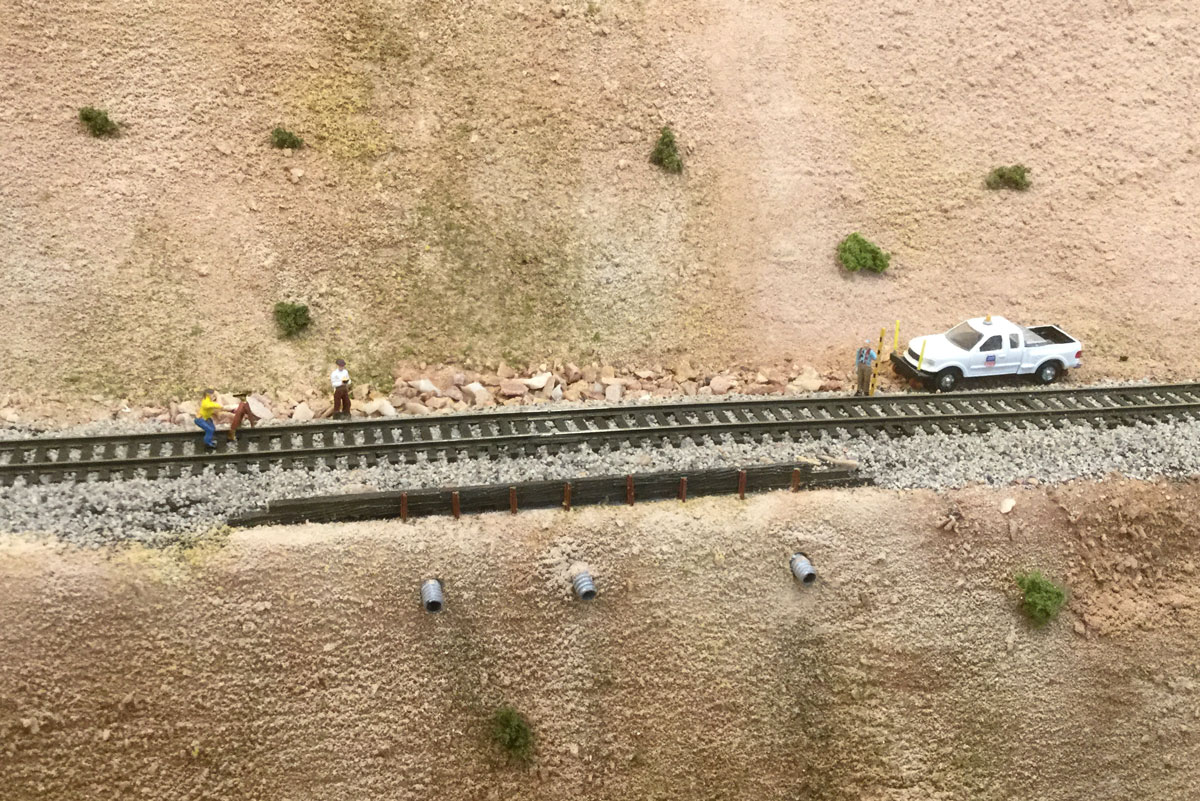
Next I added some short sections of code 40 rail as vertical supports for the
retaining wall. Then the low areas were built up with rock material
and the track was ballasted. Drain pipes were added below to show how
water is being drained from the area prone to washouts.
Here a survey crew is checking on how the track alignment was holding up several months after the washout repairs were made. So far things are things seem to be working out.