Wednesday, November 18, 2020

Upgrading wheels on old Kato locomotives

I have quite a few of the older Kato SD40, SD45, U30C, and C30-7's and I really like them for their reliability and durability.  One thing that has bothered me is the way they would rumble through any of the code 55 turnouts that I have had on my last two layouts.   No such problems with code 80 like on the Ntrak layout or the staging yards of my current home layout.   Apparently the older releases of these models have what in the hobby are called "pizza cutter" wheels as they have a flange that is almost as deep as the rail code 55 rail is tall. 

So I decided to see if I could do something about this and found that Kato USA sells packages of 6 locomotive axles with low profile wheels so I order several sets of these.

Once I got the new wheel / axle sets I wanted to make a side by side measurements of all the dimensions of both new and stock.   My first impression of the new wheels is that they look more like railroad wheels.  I also noticed that they also appear to be the same or similar as what are on some of my newer Kato releases.   Below are two photos with the dimensions I measured on each type of wheel set.


The main difference between the two is that there is a .013 difference between the flange depth.  The old wheel flanges are actually slightly larger that the height of the code 55 rail which is .055 so no wonder the wheels bumped.  The wheel itself is .015 narrower than the stock wheels but since flanges on both are right on gauge I don't believe that would make any difference but it does look better.

To change the wheels the trucks needed to be removed and then opened up to expose the axles and gears.  Then those are popped out and the new ones popped in, they are a perfect fit.  It's a good idea to clean out the cups in the brass contact frames that the axle points go in before re-assembling the trucks.


It is an $8.00 investment in each locomotive but I feel it's worth it as they are otherwise such great runners and already have DCC decoders in them.  Little by little I plan to got through the fleet with this improvement.

Saturday, November 14, 2020

Yard sequencer

In previous posts I had mentioned the use of some automation in the staging yard, here is just a bit more detail about how that works.

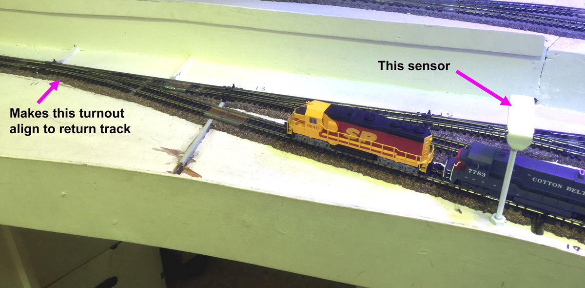
I am using Aztrax IR sensors to sense when a train arrives on one of the four staging tracks.  The sending units are in stands made from brass while the receiving units are in the tracks between the ties.  These are positioned near the departing end of each staging track.

The post on one side of the stand is 1/8 inch hallow tube and the wires for the IR sending unit are fed down through it.  The post on the other side is 1/8 inch rod that has had the end threaded for 6-32 sized nut.  Before the IR sender LED's were installed, the stands were spray painted white.  After the IR sender LED's were installed white heat shrink tubing is slipped over after a hole is punched on one side for the sender.


Referring to the control panel photo and diagram below I will attempt to explain how this works.  When a train arrives at the IR sensor pair it triggers a one second closure of the relay on the Azatrax board. The relay contact outputs of the Azatrax units are wired in parallel with the push buttons on the control panel associated with the next track but first pass through a toggle switch labeled Auto / Manual in the photo.  In the auto position the contact will trigger the turnouts for the next track and the train on that track will leave.  In the Manual position that track will be skipped and the closure will go to the next track.   This allows the flexibility to use any of the tracks and skip others in the case there is no train on that track. 


In the photo below one of those IR sensors between the ties is pointed out.  This system has been working out fairly well.  I did have to move the sensors around a bit to allow for the arriving train to coast to a stop before reaching the end of the siding.   Also it does occasionally happen that the train stops with the sensors being right between the first and second locomotive.   If this happens then when that train goes out again, the second locomotive will be mistaken as an arriving train and cause the sequence to move to the next track.


Saturday, October 31, 2020

Layout 6th anniversary - what's next

About this time in 2014 I started work on this layout and it has been slowly progressing around the train room and at this point is approaching the door to the layout room. This layout has been built one section at a time with a return loop of some sort being moved along on the leading edge to make running possible. 

So what's the next expansion ?

The photo below comes from RailPictures.net and was taken by John West in 2009.  This is on the west side of the Palisade tunnels and is one of the most photographed spots in my modeled area.  This scene is the inspiration for the next expansion of the layout in about a 4-1/2 foot space.  After entering the tunnels the tracks will cross the lift bridge across the doorway.

It was photos like the one above that got me interested in modeling this particular line and I built models of these two bridges several years before starting the layout.  Below is the photo I took of them in 2010.  They have been in storage ever since waiting for the layout to progress to this point.

I also have the tunnels portals already built.  I mentioned those in this post back in June.   So this should hopefully move along quickly through the end of the year with some of the major items already built.


Monday, October 26, 2020

Sparks yard rebuild - completion

The rebuild of the staging yard is now finished.  This took about 7 weeks to complete which was a bit less than I had expected.  All 4 staging tracks in the main yard plus the siding on the return track are available for use and I have been running various types of trains through to verify everything is working correctly.


Back in this April post I explained how a section of the return track was used to activate a current sensing unit that would cause the Wye turnout to automatically align for the yard exit.  Because the new yard has a siding on the return track I was not able to do it the same way so an Azatrax IR sensor was placed between the end of the siding and the wye turnout to trigger the turnout to change.


Back in 2014 when I was building the yard I was able to do most of the original yard wiring before the yard was installed and tipped up on edge so access was easy and I kept everything nice and neat.   The wiring modifications this time had to be done with the yard in place but I really tried to keep it neat.  What did help was having the controls in the wall cabinet under the yard.  Shown in this photo are all of the turnout controls for the new setup.


There are few more things I learned from the yard rebuild that I have not had a chance to post on so those will make good topics for future posts.

Thursday, October 15, 2020

Peco turnout panic

Over the years I have used many Peco turnouts, both code 55 and code 80.  In most cases I have removed the spring that presses the points against the rails because the Tortoise motors I have used could not reliably push the point past the tension and the motor itself would keep the points against the rails.

In this project on the entry end of the yard I had used 5 of the MTB MP5 turnout motors on 4 new and 1 old Peco turnouts.  In most cases the MP5 motors can force the points past the spring tension so I did not bother to remove the spring.  The 5th turnout on the return track siding was of the old design and I did have to remove the spring as the linkage was going through very thick bench work in that location.

At the loop end of the yard I was using 3 new and 1 old Peco turnouts with Tortoise motors.  I removed the springs on all of these and everything was going well until I started to install the turnout linkages on the 3 new ones.  As I fiddled with getting the linkage into the hole on the moving tie, the tie came completely off of the points.

What I had not realized until then was that the design of the Peco turnouts had changed and the current ones rely on that spring to keep the moving tie connected to the points.  There is a wider gap between the moving tie and the head tie on the single track end.

My solution for this was to insert a .060 x .040 Evergreen styrene rod into the space between the moving tie and the head tie on the single track end of the turnout.   I used a black sharpie pen to blacken it but left it white on the bottom so it would stand out in this photo.  That tab that is covering half the strip in the middle helps to hold it into place.  I had to fully remove the turnout and do this on the work bench.

For the two turnouts that had not fallen apart I was able to slip a shorter section of styrene strip in from each side of the turnout and glue it into place with ACC being careful not to get any adhesive on the moving tie.  I was able to do this without removing the turnout.  I found it impossible to slide one longer section of strip past that tab in the middle so that is why I had to do it this way. 


Sunday, October 4, 2020

Sparks Yard rebuild - general update # 2

The work on the rebuilding of the lower staging yard, also known as Sparks is entering it's second month. All of the track work has now been completed.  The turnout motors have been installed, wired and tested for correct connections to the frogs, and the control panel has been completed.

The control circuits need to be finished for that control panel to do much.  It was originally intended to reuse the Digitrax DS64 decoders but I discovered that the MP5 turnout motors draw too much current for them so I am needing to build control circuits to replace it.  A new control circuit has now been finished for the siding that is on the return track.  This will allow momentary push button switches to control the route selection.


Below is the schematic diagram of the circuit I am working on now.   This includes the diode matrix and Set / Reset logic circuits to latch relays that control the polarity of the voltage applied to the turnout motors.  This will also allow for single push button route selection of 4 tracks in the yard.


Thursday, September 24, 2020

Updated control panel

As explained in the recent post Rebuilding of Sparks yard, a new control panel will be needed.   This is  the procedure I follow to make my control panels.

Below is a preliminary design drawn with Microsoft Visio.   Having a drawing available now would also be a good time to go over the operating scheme of this yard.  

The original momentary center off toggle switches that could route in either direction have been replaced with 6 red push button switches to select the route.  The green LED's show track selection or turnout position as they did on the old panel.  All traffic will enter through the first turnout in the closed position and pass through the yard track selected.  After going around the loop there is one more siding along the return track.  The siding turnouts are also controlled with the red push buttons. The control of that first switch is automatic using sensors just like it was before so will align itself when a train approaches to exit the yard.  The sensors can be over ridden by a pair of red push buttons.   The toggle switches will be used to control which tracks will be in use for the automatic sequencer I am planning to include using Infrared sensors.


The original control panel was made from a pattern which I kept.  This pattern was made from a scrap of hard board is seen in the photo below.  Using this ensures proper size and alignment of the mounting holes.  The new panel is made from this same pattern.

Once a design is finalized, a printout of the drawing is stuck to the acrylic sheet and taped around the edges.   After drilling, the printout is removed and the acrylic sheet is cleaned up and polished with a product that removes any small scratches.

A sheet of .030 white styrene sheet is cut to match the size of the acrylic sheet.  Using the acrylic sheet as a pattern holes are made in the styrene sheet to match the ones in the acrylic sheet. Then another copy of the drawing without the switches and LED's is used as the actual display.  Using the acrylic sheet again as a pattern two or three of the switch holes are cut out from the drawing using a hobby knife.  The drawing is then sandwiched between the acrylic and white sheets and switches are installed in these holes so that everything stays aligned and then all the other holes can be cut out.


Since this panel was made the same size as the original, it will fit right into the original housing.  Almost all of the control wiring can also be reused with a few more added.   The red and white bottle shown in this photo is the product I use to polish out any small scratches on the acrylic sheet.


Friday, September 18, 2020

Sparks Yard rebuild - general update # 1

This yard rebuild project started around September 1st.  My plan is to push on with this through the fall and will be posting regular general updates along with posts on specific items as needed.  This is the first general update.

On the entry end next to the helix all 5 of the turnouts and Tortoise motors were removed.  Enough of the track and road bed was removed so a smooth transition from old and new could be achieved.   3 new Peco turnouts were assembled into a yard ladder on the bench and then installed and integrated into 4 of the existing yard tracks.  The turnout in the upper left corner will create the return loop and still needs to be installed.

At the other end (the loop end) of the yard the 5th track was realigned to be a single siding off of the return track.  In this photo the remnants of the old road bed can be seen.  The remaining 4 tracks have been cut off at this end of the yard and this yard ladder will be worked on when the entry end is finished.


Monday, September 14, 2020

Modifying guardrails on Peco turnouts

Almost 30 years ago I attended an informal clinic during an Ntrak club meeting on modifying Peco turnouts by adding a .010 shim to the inside of each guard rail to prevent the inside wheel flanges from hitting the frog.   This method became something of a standard for the members in the group and it is something I have always done prior to installing Peco turnouts on my home layouts and Ntrak modules.   I don't add this shim to my code 55 turnouts on my Asia prototype modules as some of the equipment run on that layout has thicker flanges and the shim would make the guard rail too tight. 

This photo illustrates what happens when the space between the outer rail and guard rail is too large.  When allowed to slide inward the inner tab of the gauge can hit the frog.


These are the materials I use for this project.

Super glue, Black sharpie pen, Hobby knife with new blades, .010 styrene strips about .125 in width, several tooth picks or push pins.


The strips are cut to a length just a bit longer than the guard rails and one side is blackened with the sharpie pen.


The side that is not blackened gets a fine bead of the super glue along it's length and is placed into the space between the rail and the guard rail with the glue side facing the guard rail.  Tooth picks or push pins are pushed into place to hold the strip against the guard rail while the super glue sets.


Next the excess strip is carefully cut away with a hobby knife making it flush with the guard rail.  The rails are used as a guide.  Any excess of the strip that extends beyond the guard rail is also removed.  This is where a nice new blade in the hobby knife pays off.


The shim should match the height of the guard rail and the edge is colored with the black sharpie pen.  As seen in this photo the gauge passes through without the inner tab hitting the frog.