Saturday, June 26, 2021

Techinque for painting lococomotive handrails.

Most railroad have had a practice of painting the handrails of their locomotives and cabooses in a contrasting color as a safety measure.   Sometimes this practice is extended to the edges of the steps.  SP and UP used white Many of the older Kato and Kato made Atlas locomotives I have on the layout did not come with painted handrails. 

On these models the handrails and walkways are a separate assembly that is made of a durable and smooth plastic a little different than the other components.  It is easier to paint the handrails with this assembly removed.

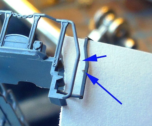
On some of these models it is not uncommon to find a bit of flash on the handrails.  Referring to the photo below, it is not very noticeable in the basic gray color so I placed a bit of white paper behind it.   Once the handrails are painted, the flash is more noticeable so it's best to remove it before painting.  These small flashes can be removed with a sharp Exacto blade.  After this I give the assembly a good washing with warm water and dish soap using an old toothbrush and then letting it dry before painting.   


That durable and smooth plastic of the handrails does not stick to paint very well.  Over the years I have tried several brands and types of paint and ended up having the best results from Testors Practa Racing Finish Enamel.  This is made for R/C car bodies which are made of a flexible plastic.   Even using this paint some of the paint would flake off the handrails over time with handling the models.


Recently I had read about some modelers using spray adhesion promoters to get better results when painting such plastics.  Not finding any product like this at my local hardware store, I ordered the product shown below from Amazon.  It is clear so masking of the handrail assembly was not necessary. 

After some practice I learned the trick to using this product is to spray the hand rails at one end then let it dry to the touch, about 3-4 minutes.  Then paint the hand rails with the top coat within 10 minutes.


I have now done 5 locomotives this way with some of those shown in the photo below.  This technique is getting me the best results yet.  Over time I may go back and redo some of the others with this new technique.


Thursday, June 17, 2021

Making the lift gate more visible

The lift gate across the entry doorway to the train room is about chest height on me from inside the room and about neck height when entering the room because of the ramped entry.  One day my wife came looking for me in the train room and did not notice the lowered gate and hit her head on it.  Both she and the gate were OK but it became a priority to make the gate more visible.

The first step was to visit the local hardware store and purchase 2 packages of this reflective tape shown on the left.

The tape is 2 inches wide and 24 inches long.  This was just right to fit along the edge of the gate on both sides.


On the same trip to the hardware store I found some 1/2 inch aluminum channel.  I used this channel to mount bright red LED's on each side of the gate.  These LED's turn on whenever the gate is in the lowered position.   Part of the channel and how the connections are made under the gate are shown in the photo below.


So this is what the gate looks like now when entering the train room.   The multi pair cable seen on the right end of the gate is for the LED's


At around the same time the gate interlock circuit stopped working.  What had happened was that when the magnetic switch on the gate opened when the gate opened, the collapsing magnetic fields on the 5 automotive relays were sending a surge of voltage back to the switch contacts until they burnt out.  The common practice to have a diode across the relay coil to prevent this.  I normally do this on my PC board mounted relays but neglected to add it this time.  Surprised I got away with it as long as I had.  So the automotive relays got replaced with some relay modules that are designed to interface with the outputs of Arduino micro controllers and have isolation circuits on their inputs so should not have any more problems.  These were mounted on the same board under the Palisade Ranch area that the automotive relays had been.  Referring to the photo below the set of 4 on the right control the DCC connection to the tracks on the gate and it's approaches, one for each rail.  One relay in the set of 2 on the left are for the LED's on the gate.


Saturday, June 12, 2021

A new layout video

I recently added a new video of the layout to my YouTube channel.  This one is a tour of the Western Pacific or eastbound paired track following a manifest freight past several scenic locations.

https://www.youtube.com/watch?v=epczlIs0zFk&t=6s


Sunday, June 6, 2021

One more bridge

There are already 6 through truss bridges on the layout but I will be adding one more in the next expansion of the layout.  This one will represent the bridge that was on the Southern Pacific line on the east side of the Palisade tunnels which served the line for more than 100 years but was demolished by a derailment in 2008.


For this bridge I choose to use the brass kit from Micron Arts.  I have only done small brass kits up to the point and this by far will be the most complex one I tried.   I've had this kit stashed away for some time and honestly have been a little intimidated by it's complexity.


The most difficult part seemed to be the first step of the kit assembly.  I found that adding the webbing to the vertical uprights to be quite challenging.  After trying both soldering a gluing these and destroying some of the webbing parts I gave up and decided to leave the webbing out.  I cleaned up the solid parts of the vertical uprights and pressed on and then things went together more smoothly.


Taking my time in building this kit it still went surprising fast.  I was soldering most of the parts and did not have to wait for any glue to dry.  The finished assembly was quite strong and sat squarely on it bridge shoes.  In the photo below it is placed in about the location where it will eventually be installed.

Somewhere I read that brass models should be soaked / washed in vinegar before painting to slightly etch the surface so the paint will adhere better.  I let this soak for several hours and also used an old toothbrush to wash away any solder flux that might be left in the corners.  After the vinegar soak the model was rinsed and left to dry overnight.


Lately I have been trying out some paints from Mission Models and like them.  Using my airbrush I first applied two coats of their gray primer.  The coverage was fine but it took 2 coats to get all the different angles of all the parts.


After letting the primer dry overnight, I gave the model 2 coats of what Mission Models calls tire black which is a flat black.


Now being finished except for some weathering, this will be put away until construction starts on the next expansion.  I don't expect that to happen until winter at the soonest.  The kit came with a section of code 55 bridge track the same length as the bridge.  I won't use this as I like to use a longer section and replace the bridge ties on both ends with standard ties so the joints are well clear of the bridge ends.