Monday, September 21, 2015

Helix assembly begins

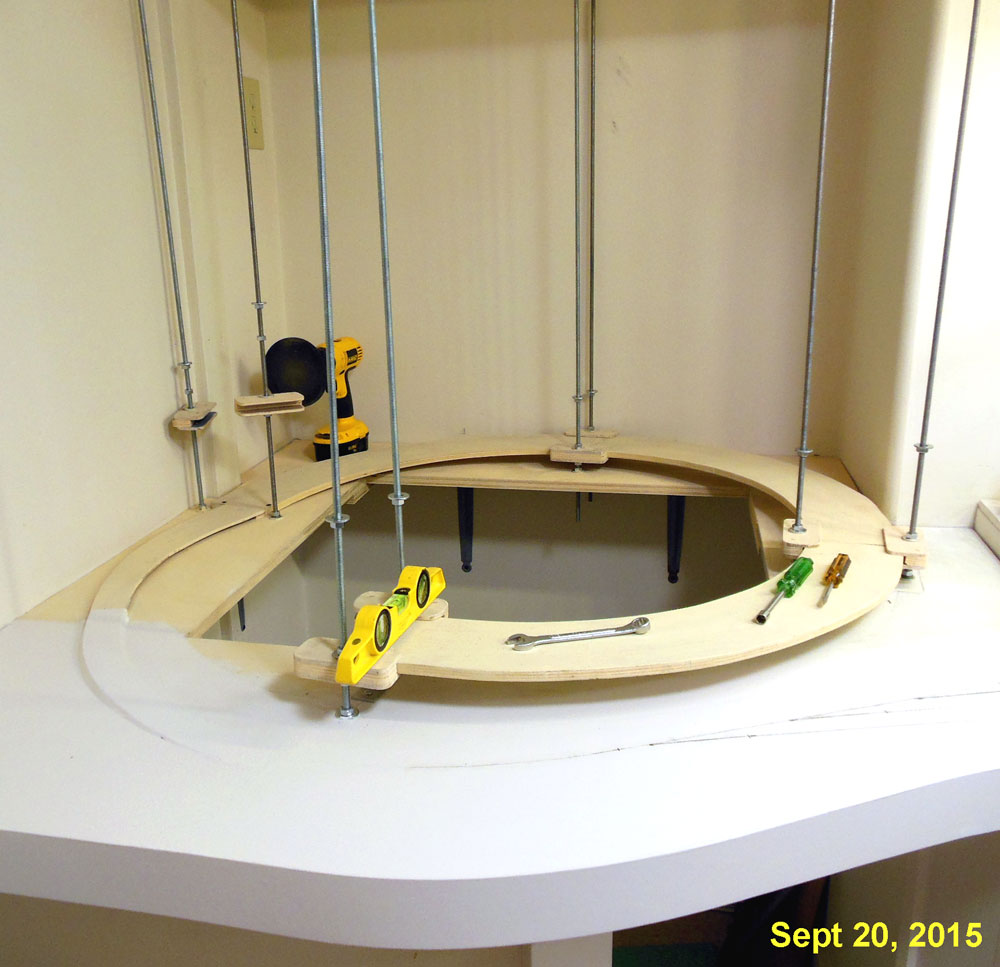
The 8 threaded rods and the first few sections of the helix are now in place and ready for cork roadbed.  The track from the lower yard will enter the helix from the bottom and the track from the upper yard will enter after 1 turn, about where that wrench is in this photo.

To create a smooth transition for the track from the lower yard to start the climb I used my router to carve out a 1/4 inch depression in the 3/4 inch base then glued and stapled a 1/4 inch plywood sub road bed in place.  This will gently start the climb up from the flat surface.

That first single track section of sub road bed meets another 1/4 inch thick sub road bed section that completes the first 1/2 inch of climb and meets the first true helix section.  It also flares out from single track width to double track width.

One of the more tedious parts of using the threaded rod helix design is threading all those nuts onto the rods.  After trying several ideas to make this go easier and faster, I settled on using the attachment for a disk sander without the sand paper.   The rubber backing has enough grip to move the nut around.  This works in both directions by reversing the rotation of the drill motor.

Wednesday, September 16, 2015

Control center for the staging yard

In last months post Installing the staging yard I had briefly shown a box that I had mounted on the wall under the yard for the purpose of mounting electronic circuits.

Here is another view of the control center before I put anything in it.  The Plexiglas door being closed causes a reflection of things that are across the room.  The top and bottom of the box are left open for air circulation.  There is an AC outlet next to the box that is on a nearby wall switch so this will be where main power for the entire layout will come from.

One of the reasons I wanted a more accessible location for the electronics is that I plan to use the layout to experiment with various control circuits.

Here is another view after I started to install some circuits for the control of the upper (WP) section of the yard.  This photo is clear because the Plexiglas door is opened.

The DS64 is for control of the 7 turnouts that are in that upper section and the circuit boards under that are something of my own design to control power connections to each of the sidings. I will show more detail on that circuit in a future post.

Also since the last post I completed the remaining turnouts needed to complete the entrance into the lower level of the yard, installed the fascia strip along the edge of the helix.  About ready to start laying out the track and actually starting the helix.

Monday, September 7, 2015

Base for the helix

For the Labor Day weekend our local hardware chain was running a "We pay the sales tax event" so I loaded up on some of the supplies to further the layout construction and that motivated me to get started on the helix.  I had already prepared some helix sections but needed to prepare the base that the helix would be mounted on.

The short wall in the corner was already in place from the construction of the layout room and what was needed was a platform on top to mount the all thread rods to.  That platform was made of 3/4 inch plywood.

4 of the helix sections were temporarily assembled into a loop to get an idea of where the rods would be.

The parts of the platform that were not going to be on top of the short wall are supported by shelf brackets.

This small space will allow access to the inside of the helix.  Notice the AC outlet and LP air nipple on the wall, this is also where the compressor is housed but can be easily rolled out of the way when necessary.

Also a few pieces of 3/4 inch plywood were used to tie in the yard to the platform that the helix will sit on.

Next I'll be continuing the tempered hardboard fascia that is on the yard section to this section.

Wednesday, August 26, 2015

Installing the staging yard


Since my last post about a week ago, I got the staging yard permanently installed in the layout. Prior to installing the yard, I removed the display case and the support brackets for the upper deck so I could spray paint the brackets white.

The yard is secured to the walls and also is supported by two large sturdy support brackets.  A third bracket was planned but after the first two were in I decided a third was not needed.  Spacing is 48 inches between brackets.

Also did some paint touch ups on the wall in this area.

I prefer not to mount all the electronics under the bench work so I used a left over 2 ft square piece of 3/4 inch plywood to make a place for wall mounting of the circuits.  This is at the entry end of the yard and has a hinged Plexiglass door to protect everything.  More on this in a future post.

Thursday, August 20, 2015

Wiring the staging yard - Turnout controls

With double ended yards, turnouts can be controlled in pairs as long as there is sufficient power from the controller for it.  I am most likely going to use the Digitrax DS64 stationary decoder to control the routes and turnouts for this particular project and have tested it and know that it's output can handle it.

This drawing represents how the turnout motors are wired in pairs to the outputs of the stationary decoder.  Green squares represent Tortoise machines.  Pairs 2 and 3 will be wired to outputs 2 and 3 but were left off for clarity.


I used 22 gauge stranded wire for this part. A different color wire twisted with a black wire is used for each pair of turnouts.  I normally like to use Euro type terminal strips for my under layout wiring but as I had so many of the standard screw type in a box I decided to use these for the turnout control wiring.

This photo shows the terminal strip at the entry end of the yard with wires going off to each of the Tortoise motors. The extra screws will be for the entry turnout that forms the reverse loop.

The 22 gauge wire can either be tinned and bent around the screws or a lug can be crimped on, both ways are shown here.

This photo shows how I am  testing each pair with 10 volts from a DC power supply.

After the yard is installed, the connections to the controller will be made from this terminal strip.

If it is discovered during testing that one turnout of a pair is operating backwards, then it is easy to reverse the connections at that turnout as shown in this photo.

At this point all of the track and wiring that can be done with the module on it's edge are done and it's time to install it in it's place in the layout.

Sunday, August 16, 2015

Evolution of a control panel layout

Back in February in the post Staging yard control panels I was starting with the control panels for the staging yard.

I had reviewed some of the control panels that I had built in the past for various layouts and decided on using a paper behind acrylic design.  I had a general idea of what I wanted the control panels to do and had built two boxes to hold the control panel and some associated circuitry from scarps of 1/4 inch plywood as shown in this photo.


Since then I have defined more specifically what I want the control panels to do.

  • Select yard ladder turnout alignment at both ends with one switch
  • Select which track is active with the same switch
  • Indicate which track is aligned and active
  • Control the turnout at entry to yard which creates the reverse loop
  • Indicate position of that turnout at entry of yard.
  • Have provision to indicate occupancy on each track
  • Have provision to select some sort of automated mode.

On all of the drawings below the big dots represent toggle switches and the small ones represent small LED's.  In this post I am addressing control for the smaller of the two yards, the WP / UP on the upper level.

This is the most basic idea I had for the layout of the control panel for the WP / UP staging yard on the upper level.  This is very similar to what is shown in the first photo.


One problem I had with this panel layout was how to control and show the position of the first turnout at the entry the yard where the return route branches off.

Using momentary center off ON/OFF/ON type of toggle switches 8 routes could be selected, 4 with the entry turnout aligned and 4 with it closed.


LED's on each staging track indicate alignment of the yard ladder and a pair of LED's for the entry turnout show it's position.  A second set of LED's show occupancy for each staging track.

This final version is a more accurate representation of the actual track plan.  The positions of the toggle switches is offset to make access easier.


A spot for a Manual / Auto switch is added for future automation plans.

Here's the finished control panel for the WP/UP staging yard.  The boxes have been spray painted with Rust-Oleum smoke gray.

I still need to finish the panel for the SP yard and wire both of them into the yard.
Sunday, August 9, 2015

Wiring the staging yard - Track feeders

With the last of the track and turnouts installed and tested on the staging yard module, it was time to finish the wiring.  I know lots of modelers hate wiring but I actually enjoy it.  Even with DCC, there is still a lot of wiring.  The wiring on most of this layout will be relativity simple but this staging yard has the highest concentration of it.

I have found those isolation plates I made to be a great place to connect the feeder wires to.  Almost all of the feeders needed were connected to one of these.

The feeders for the turnout frogs were soldered to the tie that passes through the center of the frog.
After the PC ties and isolation plates were painted weathered black, the feeder wires which are pointed out with yellow arrows in this photo are hardly noticeable.

An advantage of building the bulk of the yard as a module is that most of the wiring can be completed with it standing on edge.  I use saw horses with a 2 ft wide scrap of plywood and clamp the module frame to plywood for stability as shown in this photo.  The plywood gives me a place to put the tools and I can even do the work from a chair and be comfortable.


Although I am using DCC and may someday learn to use some sort of more sophisticated JMRI type of computer control to route trains or do some automation I'm not there yet.  So I am keeping my options open and have each yard siding isolated from the main line.  I have installed 22 gauge feeders to both ends of each siding and to each isolated section of rail in the yard ladders,  that's a lot of feeders.

I try to use the same color wires for each type of connection.  In this photo, the sidings have either red, yellow, green, or blue wire or wire markings.  White was used for the frog feeders.

It takes a bit of discipline but pays off with easier trouble shooting or modifications later.

Thursday, August 6, 2015

Mid-Summer progress report

It's been almost a month since I posted anything on this blog so just a quick update to let everyone know I'm still active on this layout.  While I've been busy with other things, I have been able to do a little bit more work on the staging yard and am getting close to having all the track work done.

Seen in this photo the entry end of the WP staging yard now has paint and cork and I've built up a 3 turnout yard ladder.

The project going on when I took this photo was to install the linkages between the turnouts and the Tortoise motors.  The Tortoises will be mounted upside down the way I did on the loop end of the SP yard.

Tuesday, July 7, 2015

Continuing progress on staging yard

Work has resumed on the upper section of the staging yard which will serve as the western terminus on the layout for the Western Pacific.

I have been building more Fast Tracks turnouts and put three right hand ones together to make the yard ladder shown in this photo.   Using the yard ladder as a guide, the cork road bed was completed to tie in the road bed from the yard tracks with that coming off the turn around loop bridge.

Also 6 more Tortoise turnout motors have been received and 3 of those will be used to power this yard ladder after the track is installed.
At the other end of the yard the section of the upper yard deck that had been left open has been completed by inserting a section of 1/2 inch plywood.

After this photo was taken the bare wood was painted both on the top and bottom to seal it.