Monday, September 21, 2015

Helix assembly begins

The 8 threaded rods and the first few sections of the helix are now in place and ready for cork roadbed.  The track from the lower yard will enter the helix from the bottom and the track from the upper yard will enter after 1 turn, about where that wrench is in this photo.

To create a smooth transition for the track from the lower yard to start the climb I used my router to carve out a 1/4 inch depression in the 3/4 inch base then glued and stapled a 1/4 inch plywood sub road bed in place.  This will gently start the climb up from the flat surface.

That first single track section of sub road bed meets another 1/4 inch thick sub road bed section that completes the first 1/2 inch of climb and meets the first true helix section.  It also flares out from single track width to double track width.

One of the more tedious parts of using the threaded rod helix design is threading all those nuts onto the rods.  After trying several ideas to make this go easier and faster, I settled on using the attachment for a disk sander without the sand paper.   The rubber backing has enough grip to move the nut around.  This works in both directions by reversing the rotation of the drill motor.

Wednesday, September 16, 2015

Control center for the staging yard

In last months post Installing the staging yard I had briefly shown a box that I had mounted on the wall under the yard for the purpose of mounting electronic circuits.

Here is another view of the control center before I put anything in it.  The Plexiglas door being closed causes a reflection of things that are across the room.  The top and bottom of the box are left open for air circulation.  There is an AC outlet next to the box that is on a nearby wall switch so this will be where main power for the entire layout will come from.

One of the reasons I wanted a more accessible location for the electronics is that I plan to use the layout to experiment with various control circuits.

Here is another view after I started to install some circuits for the control of the upper (WP) section of the yard.  This photo is clear because the Plexiglas door is opened.

The DS64 is for control of the 7 turnouts that are in that upper section and the circuit boards under that are something of my own design to control power connections to each of the sidings. I will show more detail on that circuit in a future post.

Also since the last post I completed the remaining turnouts needed to complete the entrance into the lower level of the yard, installed the fascia strip along the edge of the helix.  About ready to start laying out the track and actually starting the helix.

Monday, September 7, 2015

Base for the helix

For the Labor Day weekend our local hardware chain was running a "We pay the sales tax event" so I loaded up on some of the supplies to further the layout construction and that motivated me to get started on the helix.  I had already prepared some helix sections but needed to prepare the base that the helix would be mounted on.

The short wall in the corner was already in place from the construction of the layout room and what was needed was a platform on top to mount the all thread rods to.  That platform was made of 3/4 inch plywood.

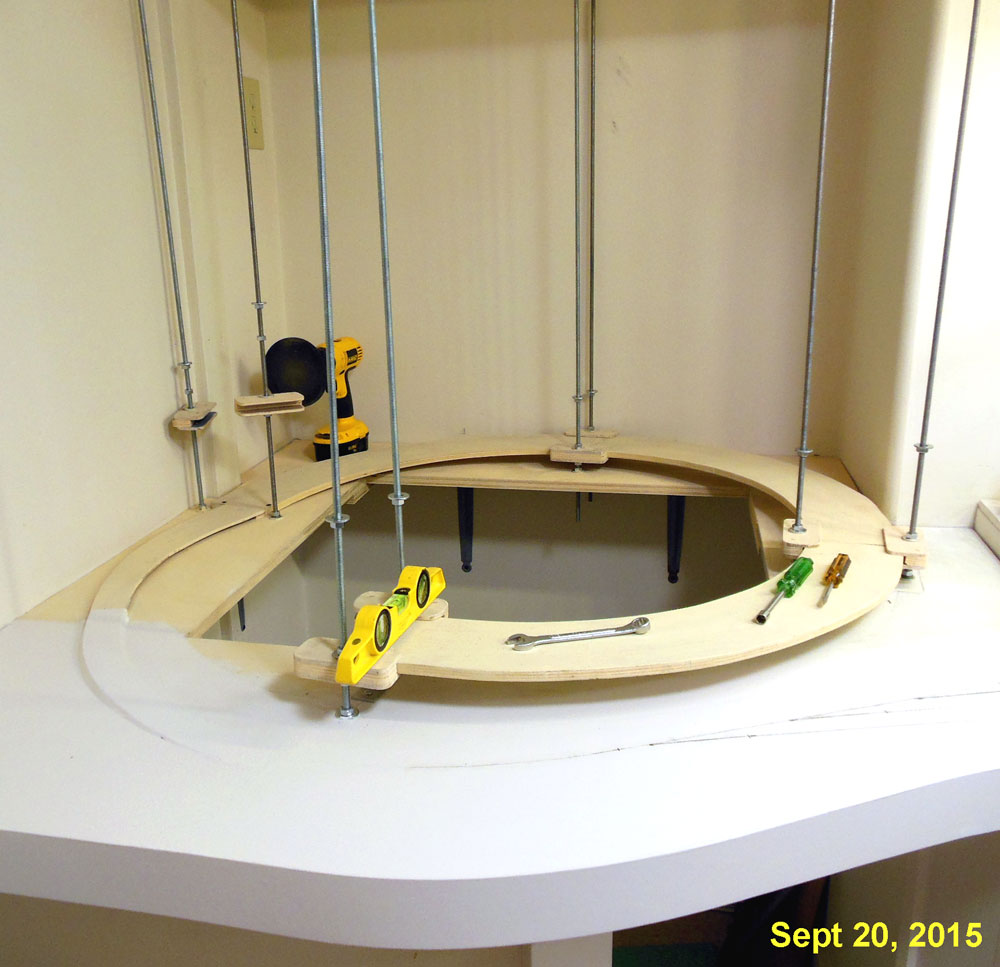
4 of the helix sections were temporarily assembled into a loop to get an idea of where the rods would be.

The parts of the platform that were not going to be on top of the short wall are supported by shelf brackets.

This small space will allow access to the inside of the helix.  Notice the AC outlet and LP air nipple on the wall, this is also where the compressor is housed but can be easily rolled out of the way when necessary.

Also a few pieces of 3/4 inch plywood were used to tie in the yard to the platform that the helix will sit on.

Next I'll be continuing the tempered hardboard fascia that is on the yard section to this section.