Sunday, December 27, 2015

New territory for the new year

After 5 turns and 14.5 inches of climbing from the lower section of the staging yard the helix is nearing completion.  The last section for the helix is a special transition section that will connect it to the Wesso section.  In this section the Atlas code 80 track will be connected to the Micro Engineering code 55 track and part of it will have scenery representing the edge of Winnemucca, Nevada so this small section will be referred to as the Winnemucca section.

To cut out this section I first made a cardboard template.  Once I was satisfied with the fit of the template I traced it's shape onto a sheet of plywood and cut this out with a saber saw.  There were still some minor adjustments to be made to get the fit just right.

To install this section it had to be put in over the all thread rods, then slide the end into the last pair of splicing blocks.  To do this I made slots for the rods instead of holes as seen in this photo.

Besides being supported by the rods and the helix splicing blocks there is also a 3/4 inch ledger along the wall where that end of the section is secured.
This end of this small section of bench work will connect to the Wesso section which I have already started to cut the parts for and will post on soon.  The holes shown in this photo are to accommodate any wiring between the two sections.


So as 2015 ends and the new year begins the layout is enter a new and exciting phase.  The most complicated bench work for the layout is now complete and section by section it can now progress around the train room.

Thank you everyone who has been following my slow progress on this layout. May you all have a safe and happy 2016.

Wednesday, December 23, 2015

The weathering contest

Work on the layout has been slowly progressing and I'll be posting more on that soon hopefully.  One side project I have undertaken during December is weathering a couple of my Micro-Trains 40 ft box cars for entry in a Micro-Trains sponsored contest on Trainboard.com.

This is the one I entered.  If you are a member of Trainboard.com all of the entries can be seen and voted on at:

www.trainboard.com 


If your are not a member, it's worth looking into.  There is no cost and they have quite a few separate boards for each modeling scale plus rail-fanning and other railroad related topics.  This months weathering contest is going to be the first of several with each month being a different type of car.

This is another car that I weathered at the same time but did not enter.  These photos were taken on one of my Ntrak modules.

Hopefully before too long both of these will be running through the Palisade Canyon.

Happy Holidays to all !  

Friday, November 6, 2015

The work train

After cleaning up the area around the helix which had gotten rather messy I am determined to be more organized in my work.

I decided to have some fun with it and made up a work train of gondolas and flat cars to bring some of  track laying materials and tools to within my reach then send it back down to the safety of the yard.


Work on the helix is moving along with a repeating  pattern of adding a section or two to the structure, then adding cork roadbed, and then the track.  Getting close to the height it needs to be.

Saturday, October 31, 2015

Helix progress


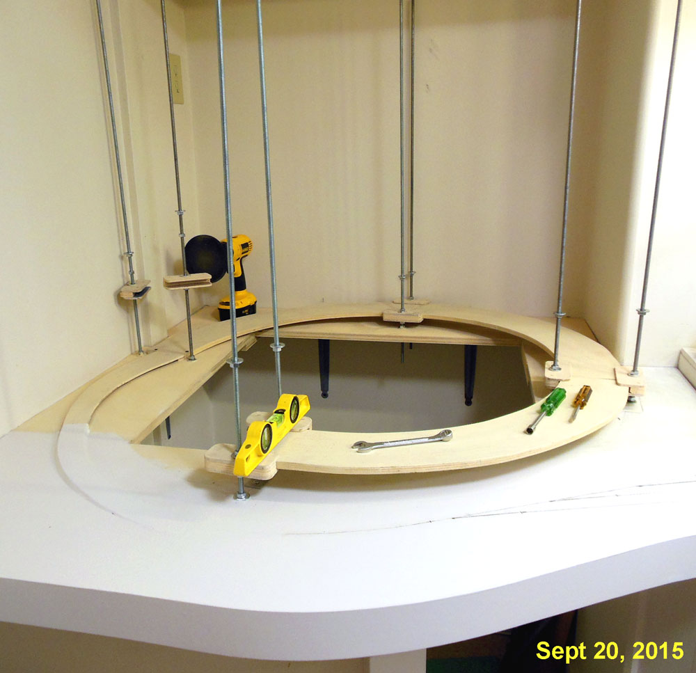
Work has been progressing on the helix.  This photo shows the helix as it currently is.  Both yards are tied in now with the outer loop from the upper yard climbing a little more than one turn and the inner loop from the lower yard climbing two full turns.

The inner loop from the lower yard and the outer loop from the upper yard each have there own power district.  Each turn of each loop will have a feeder.

I picked up a roll of 16 gauge paired wire from Powerwerx.com to use as the main bus that will connect the inputs of all the PSX modules in the layout to the DCC system.  That is the black and red wire shown in this photo.  The outputs from the PSX power district modules are 18 gauge.


One of the reasons I am using the threaded rod design is to have the ability to experiment with the performance of equipment in pulling a given train up the grades and make adjustments if needed.  The last layout had 4 % grades which worked fine but those were short and the trains I ran on that layout were normally only 8 or 9 cars long.  I knew the grade would have to be less than that on the helix.

I started out with a rise between turns on the helix of 3 inches.  This calculated out to being 2.5 % on the outer loop and 2.8 % on the inner loop.  Then I began to run trains up the helix with various types of cars and locomotive.  I plan to run locomotives in pairs on most trains and most of the sidings will hold about 20 or so fifty foot cars.  With the 3 inch rise the 6 axle units did fine but the 4 axle units would start to loose traction about the time the full train was on the grade.  So I began to adjust the levels of the helix downward.

What I settled on was 2 - 3/4 inches between the levels.  That 1/4 inch seem to make a big difference.  Both 4 and 6 axle pairs of  locomotives can now pull trains longer than the staging sidings up the helix.  With 1/2 inch thickness of the decks, there is 2 - 1/4 inch of clearance which is plenty for the highest cars and my small hands still easily reach between for cleaning track for re-railing a car.  So far, with all my testing not a single car or loco has derailed within the helix.  So the final grade on the helix is going to be 2.3 % on the outer loop and 2.5 % on the inner loop.

Once I decided on the space between levels, I cut a piece of scrap material to use as a height gauge.  Adding the 1/2 inch thickness of the plywood structure to the 2-1/4 inch space make each turn lift 2 - 3/4 inches.


Another tool I made was a double ended guide with a stop that rest at the inner edge of the deck and lengths for the inner and outer loops.  Once the lines are drawn, the installation of the cork road bed and track goes easily, two sections for half a loop at a time.


I have noticed that the helix sections seem to have a little twist in them after being installed which makes the spacing vary a bit between some levels.  While this does not seem to affect the operation in any way I would still like to keep the spacing consistent so I may add some thin spacers between the threaded rods.

Sunday, October 25, 2015

A simple voltage regulator

In my recent post Powering panel LED's from DCC signal I showed how I used the fact that DCC power was being switched on and off on the staging tracks to activate the track selected LED's on the control panel.  I also have LED's on the control panel to show the position of the turnout that creates the reverse loop.  I did try out connecting to the DCC signal and switching one side through the contacts on the Tortoise switch motor but the LED's did not turn on and off reliably for some reason.  So a DC power source was going to be needed for these and other LED indicators around the layout.  I already had an unregulated 12 volt DC power bus set up to operate some of the electronics around the layout but for LED indicators so I made up a small regulator board for this purpose.

This photo shows the 5 volt DC voltage regulator mounted inside the control center.   This small PC board measures 1.875 x 2.875 inches.  The heat sink may not be needed for light duty applications but I had it in my stash of parts so included it.


Here is the schematic for the circuit.  The .1 uf capacitor may not be necessary if the circuit is just powering LED's.  I have found in the past these regulators can have some noise on the output that can create problems for logic circuits and by habit always include it in my regulator circuits.


Parts List

  • 7805 voltage regulator (Radio Shack 2761170)
  • (2) T3 LED's
  • 1.8 K ohm, 1/4 watt resistor
  • 470 ohm, 1/4 watt resistor
  • PC board (Radio Shack 2760150)
  • (2) 2 position terminal blocks (Mouser 158-P02ELK508V2-E)
  • .1uf, 15 volt tantalum capacitor (Jameco 33486)

The parts I used were all items from my parts stash.  The vendors and part numbers are shown as an example, these are common parts available from many sources.


Here is a close up of the control panel for the upper section of the west staging yard showing the LED's for the return loop turnout being activated.

On my panel pushing any track selection switch to the right sets the turnout to the aligned route shown here.  Pushing them to the left sets the turnout to the diverging route.


Monday, October 12, 2015

1 year since construction started

It's been just about one year since construction started on the layout.  Here's what got done on the layout in that one year.

  • Staging yard bench work built, track laid, wiring done, and yard installed.
  • 15 feet of LED layout lighting installed.
  • Yard control panels started and one completed.
  • Started the helix.

Today I built the little bridge section seen in this photo that connects the upper level staging yard to the outer loop of the helix.  This section will support the turnout that creates the reverse loop for the upper yard.  Helix progress has been stalled until this is done.  It will be the last of 16 code 80 turnouts associated with the staging yards.

The helix design has been working out really well so far.  The lower level yard is fully installed and various types of trains that been run up and down the helix to iron things out.  Turnouts on the lower yard have to be moved by hand as the control system for that part is not done yet.

So what will I accomplish during the second year ?  Well, I'm looking forward to finishing the helix and building the bench work Wesso Junction and Carlin sections.  I'm also looking forward to working with the code 55 track that will be used after the helix is done and of course starting some scenery.

Tuesday, October 6, 2015

Powering panel LED's from DCC signal

When I was checking the yard ladders for power I was using an LED wired in series with a resistor.  It occurred to me that were a track circuit was being switched on or off the indicator light could also be powered from the track.

This is the control panel for the upper or WP yard.  The LED for track 3 is lighted indicating that is the track that is energized and the turnouts aligned for.  The indicators for the turnout on the lower left are not yet connected.


The occupied LED's were put on the panel with the plan to do something with occupancy detection later.   Those will most likely not be powered by the DCC signal.


Here is the back side of the control panel showing the connection.  The track selected LED signals are the wires connected to the green terminal strip.  The current limiting resistors on the PC board are 330 ohms.

The other end of those wires are simply connected to the terminals for track power.  To keep things straight I color coded the wiring for the tracks on this yard as follows 1 = Red, 2 = Yellow, 3 = Green, and 4 = Blue.   This photo shows the connections for tracks 3 and 4.

Monday, September 21, 2015

Helix assembly begins

The 8 threaded rods and the first few sections of the helix are now in place and ready for cork roadbed.  The track from the lower yard will enter the helix from the bottom and the track from the upper yard will enter after 1 turn, about where that wrench is in this photo.

To create a smooth transition for the track from the lower yard to start the climb I used my router to carve out a 1/4 inch depression in the 3/4 inch base then glued and stapled a 1/4 inch plywood sub road bed in place.  This will gently start the climb up from the flat surface.

That first single track section of sub road bed meets another 1/4 inch thick sub road bed section that completes the first 1/2 inch of climb and meets the first true helix section.  It also flares out from single track width to double track width.

One of the more tedious parts of using the threaded rod helix design is threading all those nuts onto the rods.  After trying several ideas to make this go easier and faster, I settled on using the attachment for a disk sander without the sand paper.   The rubber backing has enough grip to move the nut around.  This works in both directions by reversing the rotation of the drill motor.

Wednesday, September 16, 2015

Control center for the staging yard

In last months post Installing the staging yard I had briefly shown a box that I had mounted on the wall under the yard for the purpose of mounting electronic circuits.

Here is another view of the control center before I put anything in it.  The Plexiglas door being closed causes a reflection of things that are across the room.  The top and bottom of the box are left open for air circulation.  There is an AC outlet next to the box that is on a nearby wall switch so this will be where main power for the entire layout will come from.

One of the reasons I wanted a more accessible location for the electronics is that I plan to use the layout to experiment with various control circuits.

Here is another view after I started to install some circuits for the control of the upper (WP) section of the yard.  This photo is clear because the Plexiglas door is opened.

The DS64 is for control of the 7 turnouts that are in that upper section and the circuit boards under that are something of my own design to control power connections to each of the sidings. I will show more detail on that circuit in a future post.

Also since the last post I completed the remaining turnouts needed to complete the entrance into the lower level of the yard, installed the fascia strip along the edge of the helix.  About ready to start laying out the track and actually starting the helix.

Monday, September 7, 2015

Base for the helix

For the Labor Day weekend our local hardware chain was running a "We pay the sales tax event" so I loaded up on some of the supplies to further the layout construction and that motivated me to get started on the helix.  I had already prepared some helix sections but needed to prepare the base that the helix would be mounted on.

The short wall in the corner was already in place from the construction of the layout room and what was needed was a platform on top to mount the all thread rods to.  That platform was made of 3/4 inch plywood.

4 of the helix sections were temporarily assembled into a loop to get an idea of where the rods would be.

The parts of the platform that were not going to be on top of the short wall are supported by shelf brackets.

This small space will allow access to the inside of the helix.  Notice the AC outlet and LP air nipple on the wall, this is also where the compressor is housed but can be easily rolled out of the way when necessary.

Also a few pieces of 3/4 inch plywood were used to tie in the yard to the platform that the helix will sit on.

Next I'll be continuing the tempered hardboard fascia that is on the yard section to this section.

Wednesday, August 26, 2015

Installing the staging yard


Since my last post about a week ago, I got the staging yard permanently installed in the layout. Prior to installing the yard, I removed the display case and the support brackets for the upper deck so I could spray paint the brackets white.

The yard is secured to the walls and also is supported by two large sturdy support brackets.  A third bracket was planned but after the first two were in I decided a third was not needed.  Spacing is 48 inches between brackets.

Also did some paint touch ups on the wall in this area.

I prefer not to mount all the electronics under the bench work so I used a left over 2 ft square piece of 3/4 inch plywood to make a place for wall mounting of the circuits.  This is at the entry end of the yard and has a hinged Plexiglass door to protect everything.  More on this in a future post.

Thursday, August 20, 2015

Wiring the staging yard - Turnout controls

With double ended yards, turnouts can be controlled in pairs as long as there is sufficient power from the controller for it.  I am most likely going to use the Digitrax DS64 stationary decoder to control the routes and turnouts for this particular project and have tested it and know that it's output can handle it.

This drawing represents how the turnout motors are wired in pairs to the outputs of the stationary decoder.  Green squares represent Tortoise machines.  Pairs 2 and 3 will be wired to outputs 2 and 3 but were left off for clarity.


I used 22 gauge stranded wire for this part. A different color wire twisted with a black wire is used for each pair of turnouts.  I normally like to use Euro type terminal strips for my under layout wiring but as I had so many of the standard screw type in a box I decided to use these for the turnout control wiring.

This photo shows the terminal strip at the entry end of the yard with wires going off to each of the Tortoise motors. The extra screws will be for the entry turnout that forms the reverse loop.

The 22 gauge wire can either be tinned and bent around the screws or a lug can be crimped on, both ways are shown here.

This photo shows how I am  testing each pair with 10 volts from a DC power supply.

After the yard is installed, the connections to the controller will be made from this terminal strip.

If it is discovered during testing that one turnout of a pair is operating backwards, then it is easy to reverse the connections at that turnout as shown in this photo.

At this point all of the track and wiring that can be done with the module on it's edge are done and it's time to install it in it's place in the layout.

Sunday, August 16, 2015

Evolution of a control panel layout

Back in February in the post Staging yard control panels I was starting with the control panels for the staging yard.

I had reviewed some of the control panels that I had built in the past for various layouts and decided on using a paper behind acrylic design.  I had a general idea of what I wanted the control panels to do and had built two boxes to hold the control panel and some associated circuitry from scarps of 1/4 inch plywood as shown in this photo.


Since then I have defined more specifically what I want the control panels to do.

  • Select yard ladder turnout alignment at both ends with one switch
  • Select which track is active with the same switch
  • Indicate which track is aligned and active
  • Control the turnout at entry to yard which creates the reverse loop
  • Indicate position of that turnout at entry of yard.
  • Have provision to indicate occupancy on each track
  • Have provision to select some sort of automated mode.

On all of the drawings below the big dots represent toggle switches and the small ones represent small LED's.  In this post I am addressing control for the smaller of the two yards, the WP / UP on the upper level.

This is the most basic idea I had for the layout of the control panel for the WP / UP staging yard on the upper level.  This is very similar to what is shown in the first photo.


One problem I had with this panel layout was how to control and show the position of the first turnout at the entry the yard where the return route branches off.

Using momentary center off ON/OFF/ON type of toggle switches 8 routes could be selected, 4 with the entry turnout aligned and 4 with it closed.


LED's on each staging track indicate alignment of the yard ladder and a pair of LED's for the entry turnout show it's position.  A second set of LED's show occupancy for each staging track.

This final version is a more accurate representation of the actual track plan.  The positions of the toggle switches is offset to make access easier.


A spot for a Manual / Auto switch is added for future automation plans.

Here's the finished control panel for the WP/UP staging yard.  The boxes have been spray painted with Rust-Oleum smoke gray.

I still need to finish the panel for the SP yard and wire both of them into the yard.

Sunday, August 9, 2015

Wiring the staging yard - Track feeders

With the last of the track and turnouts installed and tested on the staging yard module, it was time to finish the wiring.  I know lots of modelers hate wiring but I actually enjoy it.  Even with DCC, there is still a lot of wiring.  The wiring on most of this layout will be relativity simple but this staging yard has the highest concentration of it.

I have found those isolation plates I made to be a great place to connect the feeder wires to.  Almost all of the feeders needed were connected to one of these.

The feeders for the turnout frogs were soldered to the tie that passes through the center of the frog.
After the PC ties and isolation plates were painted weathered black, the feeder wires which are pointed out with yellow arrows in this photo are hardly noticeable.

An advantage of building the bulk of the yard as a module is that most of the wiring can be completed with it standing on edge.  I use saw horses with a 2 ft wide scrap of plywood and clamp the module frame to plywood for stability as shown in this photo.  The plywood gives me a place to put the tools and I can even do the work from a chair and be comfortable.


Although I am using DCC and may someday learn to use some sort of more sophisticated JMRI type of computer control to route trains or do some automation I'm not there yet.  So I am keeping my options open and have each yard siding isolated from the main line.  I have installed 22 gauge feeders to both ends of each siding and to each isolated section of rail in the yard ladders,  that's a lot of feeders.

I try to use the same color wires for each type of connection.  In this photo, the sidings have either red, yellow, green, or blue wire or wire markings.  White was used for the frog feeders.

It takes a bit of discipline but pays off with easier trouble shooting or modifications later.

Thursday, August 6, 2015

Mid-Summer progress report

It's been almost a month since I posted anything on this blog so just a quick update to let everyone know I'm still active on this layout.  While I've been busy with other things, I have been able to do a little bit more work on the staging yard and am getting close to having all the track work done.

Seen in this photo the entry end of the WP staging yard now has paint and cork and I've built up a 3 turnout yard ladder.

The project going on when I took this photo was to install the linkages between the turnouts and the Tortoise motors.  The Tortoises will be mounted upside down the way I did on the loop end of the SP yard.

Tuesday, July 7, 2015

Continuing progress on staging yard

Work has resumed on the upper section of the staging yard which will serve as the western terminus on the layout for the Western Pacific.

I have been building more Fast Tracks turnouts and put three right hand ones together to make the yard ladder shown in this photo.   Using the yard ladder as a guide, the cork road bed was completed to tie in the road bed from the yard tracks with that coming off the turn around loop bridge.

Also 6 more Tortoise turnout motors have been received and 3 of those will be used to power this yard ladder after the track is installed.
At the other end of the yard the section of the upper yard deck that had been left open has been completed by inserting a section of 1/2 inch plywood.

After this photo was taken the bare wood was painted both on the top and bottom to seal it.

Thursday, June 18, 2015

Helix design

When I decided that I would need a helix to do what I wanted to do on this layout I studied everything I could on the Internet and examined first hand any helix that I could.  The room that I built in the back of my garage is a 20 x 10 ft rectangle but has a 2 ft bump out in one corner for part of the helix.  The net space set aside for the helix is 42 x 42 inches.

I really liked the idea of using all thread rods to support the helix because it would allow me to experiment with some different grade adjustments plus it offered the best access to the tracks.

My design uses 90 degree curved sections of 1/2 inch plywood that are 4.5 inches wides.  The radius on the outer edge of the curved sections is 20.5 inches.  Between each section a pair of splicing blocks hold the sections together and attach to 3/8 inch all thread rod.  Two 8-32 screws on each side of each section will secure the splice blocks to the curved sections.

I found that I could get 10 of the curved sections from a 4 x 4 sheet of birch plywood.  After making the first one I marked it as master and used it as a template to draw the others.


The splicing blocks are made from scraps of the sheet that the curved sections were cut from in between 1/4 inch thick birch plywood material.  The overall size of these assemblies is 4 inches x 2 inches.

Here are the results from a single 4 x 4 sheet of plywood.  The curved sections on the left have been painted. All sections will be painted prior to assembly.  This is a start, my plan is by doing some of this now, I'll be able to go right into assembling the helix after the yard is completed and installed.