Friday, December 23, 2016

More options for LED layout lighting

Within the few years that I have been experimenting with lighting my layout with LED's, many more products have become available and prices have been falling.  A19 or medium base screw in bulbs are now available in a full range of wattage equivalents and color temperatures.

I recently purchased these A19 or medium base, 40 watt equivalent, warm bright bulbs on amazon for about $3.00 each along with some sockets that have a mounting bracket for another $3.00 each.

As I have been building the layout I have realized that in many areas I do not need as much vertical clearance as I had thought and can allow for a taller lighting valance.

Here is how I am mounting these lights above the layout under the cabinets.  After some experimentation I came up with a spacing of 16 inches for an even level of lighting.   Strips of 2 inch wide plywood were mounted under the cabinets that have plywood brackets mounted every 16 inches.

So far I have put up 11 bulbs under the cabinets along the longest wall.  Shown in this photo is the area above the work bench.  A valance made from tempered hard board (Masonite) can be mounted to the same plywood brackets that the light sockets are mounted to.

Tuesday, December 13, 2016

Finishing the upper return loop bench work.

The upper return loop bench work has now been finished and installed in it's place on the layout above the Wesso section.  The 3 lighting panels from the last post are installed and the effects of the lighting can be seen in this photo.  Still need to put up a lighting valance.

Here is another view taken from inside the helix.  The LED panels can be seen lined up along the outer edge of the upper loop section.  I am happy with the level of lighting on the Wesso section except that is seems a shade darker in the back of the far corner where the dry creek is. I may need to add a couple more LED modules above that area.

Because the area below the return loop is part of the scene it needed to stay open without supports so I put the supports on top.  The frame of the bench work is also attached to the wall studs.  This makes this section really sturdy.

The cork has been laid but not the track.  It will be some time before the layout is far enough along for trains to run over this section and because it is so sturdy I plan to use this section as a storage shelf for the time being.

This photo shows two of the Anderson Power Pole connectors that will connect lighting panels shown in the last post to the 12 volt DC bus.

In the top of this photo there was a small irregular area where I just mounted a permanent panel with 2 LED panels that are wired directly to the 12 volt DC bus.

Saturday, December 10, 2016

First removable LED lighting panels completed

The first three removable LED lighting panels have been completed.  These will be for the upper return loop section with the LED's lighting the Wesso section underneath it.

These are made from 1/4 inch thick plywood with the exposed side being painted with the off white color of the train room trim so as to be more reflective.

This photo shows the smallest of the three panels leaning up against one of my module boxes with some of the details pointed out.

These panels will be held in place by inserting the tongue part in the back then tightening two or three 8-32 thumbscrews into tee nuts that will be part of the module.

The tee nuts and thumbscrews are shown here.  I bought 100 pairs so they will be handy for some other projects I have in mind.

Each of the panels has it's wiring on the back side with an Anderson Power Pole plug that will be used to connect to the 12 volt DC bus on the bench work.


Here is the largest of the 3 panels that will go under the upper return loop section.  This one also has the most LED panels on it.  I have placed these along what will be the front edge and at a slight angle inward toward the back of the module.

The plan now is for there to be removable lighting  panels similar to these under the Carlin section to light the staging yard, and under any section that is over the work benches.

Next step is to get the return loop section mounted so these panels can be installed and the effects of the lighting tested.

Friday, December 2, 2016

First photographic backdrops have arrived

The first 4 photographic backdrops have arrived.  One of these is shown in this photo temporarily set up behind the test layout above the work bench to see how it looks.


These are from Backdrop Junction.  I have two pairs of 6 ft long backdrops that are 14 inches high.  There are two different scenes that connect together and with another two that are the same scenes reversed I will be able to get 24 ft of continuous scene.  First got to get up some more panel.

Tuesday, November 15, 2016

Preparing for photographic backdrops

It is usually best to finish the backdrop before installing the bench work that is going to be in front of it.   Now that the Wesso and Golconda sections progressing nicely,  I need to install a hard, smooth paneling that will curve around the inside corners of the walls that I can then install a photo backdrop on.

Many people use Masonite but I have been using fiberglass reinforced plastic wall paneling.  It is bumpy on the finished side and smooth on the back side so I use it back side out.  This paneling had worked very well on my old layout for 11 years as mentioned in the December 2013 post Lessons learned from the old layout.  For me the advantages of this type of paneling are the thinness and the greater flexibility when rounding a corner.

This photo shows both sides of this type of paneling.  It comes in a 4 x 8 ft sheet and I cut it lengthwise to get three 16 inch x 8 ft strips.  I have cut this both on my table saw with a fine tooth blade and by the scribe and snap method.

Attachment is done with 1 inch nails on the top and bottom at each wall stud.  I tried using finishing nails but the heads of the nails tended to break through the panels so I now use 1 inch nails with a flat head.
At the seams I splice the sides of the panels facing the wall with .020 styrene.


The corners on this layout will be curved and the first one is going to be behind the dry creek scene on the Wesso section.

This photo shows that area and how I have placed the seam between two sections of panel to one side.  The first two panels were from the old layout and had been painted blue.  A notch has been cut out right at the corner so the panel could go over the bench work.


The nails and seams are then smoothed out with Spackle and then a coat of primer will put on to seal everything.  With at least some of the panels now ready I have ordered 24 ft of photo backdrop.

Thursday, November 10, 2016

East end return loop bench work

The east end of the layout is to have a return loop that will be above the Wesso section.  The Wesso section has been completed for some time but I do not want to install it until I have built and installed the end loop section that will be above it and also some of the back drops that will be behind the Wesso section.

So while I have been working on the Gloconda section in the train room I have also started bench work for the end loop out in the driveway as the weather has been nice lately.  In this photo the path of the end loop and a possible passing siding has been mocked up with Kato Unitrack.

Here is another view of this section with the bottom up.  The frame of this section is only 2 - 1/2 inches thick and will have removable panels on the bottom that will have LED light panels attached to them. This view shows one panel on and one off.

The panels will be secured all along the back by sliding a tab that runs along the back edge of the panel under a strip that is permanently attached along the bottom of the back edge of the section.  A pair of screws near the front edge of the panel will then hold the panel in place.

The end loop section of the layout will be supported by attachment to the walls and also by at least one bracket from above.  Near the center of this photo can be seen an extra support and mounting hole for one of those brackets.

There are several support frames within the end loop section.  Holes were made in these to run wiring for the track and notches were made so that the LED light wiring that will be on the panel will not be pinched when the panel is installed.


This east end return loop will be connected to another helix that will carry the tracks down to the Carlin section.  With so much track length being within the helix I am considering using some sort of serial staging for the east end of the layout.

Friday, November 4, 2016

Land forms for the Golconda section

After finishing the basic bench work I used a similar method as I had done on the Wesso section to create the contours of the land.  Insulation board was cut and shaped with a inexpensive steak knife to get the basic shapes I wanted.  This time I decided to place a layer of plaster cloth over the shaped insulation board to further refine the shapes.  This will later be followed up with a brushed on wet coat of sheet rock mud.

The bridge abutments were cut from 1/4 inch plastic and after fitting them into the correct positions were attached with Liquid Nails adhesive.  The masking tape is to protect them from getting any plaster or sheet rock mud on them.

Friday, October 28, 2016

Bench work for the Golconda section

Back in the July post First crossing of the Humboldt River I described the scene I wanted to create for the next section of the layout and had a good start on a pair of bridges.  At that time I had named it the Golconda section as that is the name of the location where this scene is located.

Here is a photo of this section right now with the bench work completed. Because it is quite a bit smaller than the Wesso and staging yard sections I was able to build it entirely from scraps left over from those.  The deck is from scraps of 1/4 inch plywood with the middle section set lower for the river.


This section will be an anchoring point with a sturdy metal bracket similar to those used on the staging yard on each end.  The Paint booth will fit between the bracket and under this layout section.

Sunday, October 23, 2016

Two year anniversary for the layout

It was around this time two years ago that I started work on this layout.  One year ago I marked the first anniversary by noting what had been accomplished up to that point and and making goals for the next year.   Looking back now I am actually pleased with the progress, here is a brief review of the goals I set out for myself one year ago and their current status.

  • Complete lower helix - Done !
  • Bench work for Wesso and Carlin sections - Done !
  • Start some code 55 track - Yes, on the Wesso section.
  • Start some scenery - Yes, on the Wesso section.

So here is what I hope to accomplish on the layout over the next 12 months.
  • Complete the 3 ft Gloconda section including scenery with the bridges crossing the river.
  • Build and install the upper return loop section that goes above the Wesso section.
  • Install LED lighting under the upper return loop that will light the Wesso section
  • Permanently install the Wesso and Gloconda sections after installing photographic backdrops.
  • Add the bottom panels with LED lighting to the Carlin section so the staging yard will be lighted.
  • Build a temporary return loop section that can be moved as the layout progresses allowing running on the completed sections.
  • Start bench work on the section that will come after the section with the bridges.

I made up this drawing to show how the different sections relate to each other.  Right now all of the work is going on at one end of the layout room.  The plan is that as the layout is extended around the room the section labeled "Gloconda" will eventually connect to the section labeled "Carlin".

Most of what is shown here are the parts of the layout that will be double decked with most of the rest of the layout being single deck.


This should keep me busy for the next 12 months.

Sunday, October 16, 2016

On the road again - Scranton, PA

On the last full day of our recent trip to the east coast we drove from Sayre, PA to Mount Laurel, NJ and had enough time to make a short visit to the Steamtown National Historical Site in Scranton, PA.  The site is in downtown Scranton and was originally owned by the Delaware, Lackawanna, and Western Railroad which was most commonly known as the Lackawanna.

The focal point of the historic site is the round house.  Most of the round house has been converted to museum displays while several bays remain as a working repair and restoration facility.
We were there on a Monday and it was fairly quiet.  I understand that on the weekends there are back shop tours and excursions available.

The 90 ft turntable is still in use to move equipment in and out of the roundhouse bays used for repair and restoration.

Within the area around the turntable are parked several locomotives and rolling stock such as this Eire Lackawanna caboose.

The Eire Lackawanna was created in 1960 by the merger of the Eire with the Lackawanna.

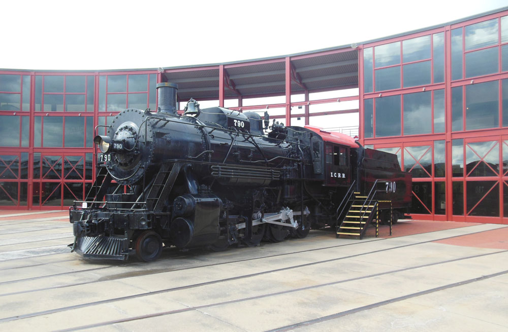
There are a number of interpretive displays to explain in detail how a steam locomotive works including this actual locomotive with many cut away sections so the visitors can see what is inside.

Visitors are able to view the part of the working part of the roundhouse from elevated walkways.  I thought they really did a great job of utilizing the round house space and that the different types of areas tied in really well together.


While the exit was well marked on the highway, once we got into downtown Scranton we had trouble figuring out exactly where the entrance to the site was.

I have marked up a Googlemaps screen shot showing the entrance from Lakawanna Ave. marked with a red arrow.


There is so much to see I could have easily spent the whole day there and really hope to be able to do that some day.  It is well worth the stop even if you only have a couple of hours like I did.

Saturday, October 8, 2016

On the road again - New Hope, PA

During the last part of September and the beginning of October Nona and I took a trip to visit family to the northeastern US.  There were a couple of opportunities during this trip to do railroad type things.

The New Hope and Ivyland Railroad is a short line running on part of the former Reading Railroad Bethlehem branch through Bucks County Pennsylvania north of Philadelphia.  

This is a working freight railroad which also operates as a heritage railroad and offers passenger excursions.

This is the station in New Hope, Pennsylvania.

The New Hope and Ivywood railroad has a variety of steam and diesel locomotives on their roster.  This one looks like it could have come from the Canadian Pacific but I could not find any reference to this number so it may be an more recent acquisition.

Our train was pulled by this C30-7 which had previously owned by the Seaboard and then the CSX.   It has been fully repainted in the New Hope and Ivyland's paint scheme.

At the New Hope station they use a freight height platform which made boarding easy.

The New Hope and Ivyland has been operating passenger excursions since 1966 and our Philadelphia area cousins had been on this train before.   They thought we would also enjoy it and they were right.

Here is an interior shot of the car we were riding in which included a bar.  The six of us had the car to ourselves.

Here is Nona enjoying the train ride through the countryside.  It was an enjoyable day during which we also explored the towns of New Hope, PA and Lambertville, NJ which are on opposite sides of the Delaware River from each other.

Here is a link to the New Hope and Ivyland RR website.

Thursday, September 15, 2016

Redo of the test layout

It seems that I took most of the summer off from working on this layout as I have been working on my Japanese modules which will be in a show this weekend, and my wife and I have been doing a bit of traveling.  This fall I will get back to work on the Palisade Canyon layout.

In May of last year in the post Experimenting with reverse loops, I described the shelf layout above my work bench.  That Kato Unitrack layout had been set up to have a dog bone loop with two reverse loops.  It also had an outer loop with a siding and the two loops were connected with a double crossover.

After the electronics for the reverse loops was transferred to the main layout's staging yards the inner loop has not seen much use.  The outer loop is used to test run locomotives and is able to be switched between DC and DCC.

Recently I re-configured the layout and the result is shown here.

The siding was removed from the outer loop and the inner loop now has a 3 track staging yard and no reverse loops.  The two loops are still connected with the double cross over.  The purpose of this setup will be to experiment with some different methods of staging yard control using Micro-controllers and IR detectors to possibly add automation.

Eventually as the main layout works its way around the room, it will displace this temporary layout.  Until then I'll enjoy this small layout.

Tuesday, July 5, 2016

First crossing of the Humboldt River

As mentioned in previous posts both rail lines cross the winding Humboldt river many times between Winnemucca and Carlin, Nevada.  In some places only one line crosses the river and in others both lines.  The first full crossing of the river going east from Winnemucca is just east of Golconda.

This shot of the actual location is from Bingmaps Bird's Eye View and is looking toward the south so the orientation is the same as the layout.  The WP line is in the foreground crossing the through truss bridge and the SP in the background crossing the ballasted concrete deck bridge.


I found this nice shot on the internet.  This location is actually a bit east of my modeled area but is typical of the types of bridges used and of the spacing between the lines.

In full size this photo shows great detail of the concrete bridge and I am using it as a reference to scratch built a model of it.


I had considered using the BLMA segmented concrete bridge kit but it only has 3 pilings per bent and this prototype has 6 so I am scratch building this one.  A couple of years ago I scratch built 3 similar type bridges for one of my Ntrak modules.  Those bridges were based on parts from a Tomix kit and were not intended to be of any specific prototype but some of the techniques learned on those will be applied to this bridge.

Here is my start on the segmented concrete bridge using some 1/8" thick clear acyrilic and some 1/4" plastic materials as a core and then adding the more features with Evergreen strip polystyrene materials.

To model the through truss bridge I am building another Central Valley Model Works kit which I have shortened from 4 sections to 3 to match the prototype.  I already have two of these I've done for the Palisades area of the layout.


This scene will be on the next module which is going to be called the Golconda module.  It will be a small module only about 3 ft in length and will be above the paint booth.

Thursday, June 30, 2016

Controls for Wesso's double crossovers

Over the past couple of weeks I've been installing the turnout motors and controls.  For the interchange at Wesso there are three different possible routes.  The three drawings below illustrate the three conditions.  The SP traffic is shown in red and the WP traffic is shown in orange.

All turnouts aligned for SP westbound and WP eastbound.

East crossover diverging and west crossover aligned for westbound joint line to WP shown in orange.  SP trains hold at western approach.
West crossover diverging and east crossover aligned for SP to eastbound joint line.  WP trains to hold at western approach.

Looking at these drawings I realized that the turnouts could be operated in pairs and only require two control outputs.  I wanted to use push buttons this time and wanted an indication of which of the three conditions was active.

The control panel I came up with uses the same method used for the staging yard control panels but with simple graphics instead of a track diagram. This will have a more finished look to it once the fascia board is installed.

My push buttons are only Single Pole Single Throw (SPST) so I needed to build a small circuit for Double Pole Double Throw (DPDT) relays and for logic to control the LED's on the panel.  I used an old ribbon cable for a floppy drive to connect the board to a terminal strip which then connects to the panel.

Here's a closer view of the circuit I made and the DS64.   Only two outputs and 3 inputs of the DS64 is being used but I may use the remaining inputs and outputs to control turnouts on the eastern staging yard that will be directly above this module.

Again I am doing all the wiring before installing the module into the layout.  Here is the module laying on it's back where I can sit on a stool to comfortably do the work.  Temporary connections are made to power supplies and Loconet.

I have been marking my Tortoise motors with a "C" for closed and "T" for thrown as shown in this photo.  This helps when you can't easily see the turnouts to determine position while working on the controls.

Tuesday, June 21, 2016

Trying out a new ballasting technique

With the track on the Wesso module all done and tested it was time for ballast.  I plan to finish the module as much as possible up to about 6 inches of the ends before installing it permanently in place on the layout.

I normally like to use HO ballast for track to have a contrast of texture with the N scale ballast I use for such things as gravel roads.

For this layout I have selected the Arizona Rock & Mineral products shown in this photo.  The eastbound and westbound lines will use different color ballast representing two different railroads.

On the back of the labels on the bags of ballast it was suggested that first placing black cinder ballast along the lower edges would result in a more realistic looking roadbed.  I used N scale black cinder for this part.  This photo shows a section of track with only that ballast applied along the edges.

Before starting the ballast on the layout I had tried out this technique on a diorama. A section of the finished track on the diorama is shown in this photo.  Any bare spots show the underlying smaller, darker ballast and not the cork.


Also I noticed that having the N scale ballast secured along the lower edges of the road bed help keep the main ballast from eroding when applying the 50 / 50 white glue and water solution.  So I would have to say that I do like this technique and plan to use it on this layout.

Sunday, June 5, 2016

First scenery on the layout

Most  people get the track all done before starting any scenery and I normally do the same.  This time with the ballasted wood trestle on the Wesso module I felt that I needed to get the scenery done in the areas that would be directly under the trestle before installing the trestle.
Here's another shot at a higher angle showing a larger area.  Once I got started doing scenery I got a little carried away and ended up doing almost half the module.   Track is all in, wired, tested, and painted.  Next will come the ballast then some touch ups the scenery.