Showing posts with label Turnout motor. Show all posts

Monday, December 4, 2023

Tortoise motor noise problem

In a post earlier this year, I reported about a Digitrax DS64 that had inputs that were no longer working.  I had replaced the DS64 with a control circuit I built myself.  This was on my WP staging yard. Recently I have been having some issues with the circuit that controls the SP yard as well. 

Specifically, the turnout at the wye that creates the return loop would sometimes cause the turnouts that control the siding on the return track to switch.  As this wye turnout can be triggered by a train passing a sensor while the train is still passing through the siding turnouts, this would cause a derailment.


The turnouts on this staging yard are controlled by three different circuits as shown in this photo.  One controls the yard ladder, another the wye turnout and the third controls the siding turnouts.


I suspected that some sort of noise was getting onto the input connections of the board that controls the siding turnouts.  This was confirmed by monitoring the inputs with an oscilloscope. The inputs to the circuit are normally high at +12 volts and when the buttons are pressed or the IR sensor activated, they go low to 0 volts.   On the oscilloscope it could be seen that spikes were randomly occurring when the wye turnout motor was running and occasionally when the spike was large enough the inputs to the siding control board were being activated.


What was happening here was that arcing between the motor's commutator and brushes on the wye turnout were creating these spikes and the magnetic field from those spikes on the motor wires was being picked up by the input wires on the siding control circuit.    Notice in the photo of the circuits how many of the wires are bundled together.  This can contribute to this happening as can the age of the motors.  The Tortoise motors on this layout range in age from 9 to 30 years old.  When I built this staging yard 9 years ago I twisted the motor wires which is supposed to help eliminate this problem and it did for a long time.

After reviewing several YouTube videos and some experimenting at the work bench I found the most effective solution was to suppress the noise as close to the source as possible.  I added a .01uf ceramic disc capacitor from each motor lead to the case of the motor.  After removing the motor from the Tortoise case, a pair of .039 holes were drilled in the circuit board at the locations pointed out with green arrows in the photo below.
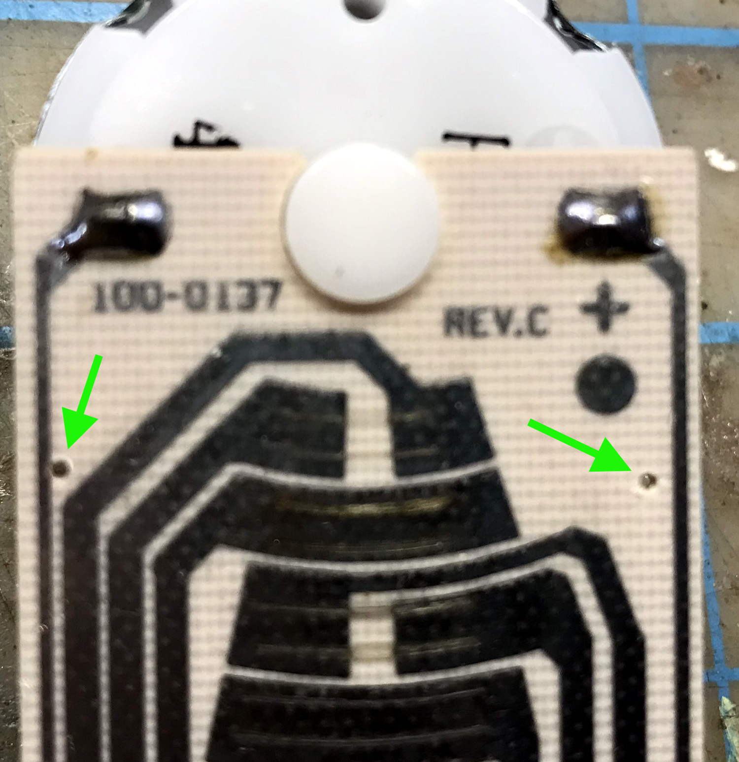


One lead of the capacitors were soldered to the case as shown in this photo.  To get a solder connection to the case I first scraped that spot on the case with a file and used flux and a hot soldering iron.  The other lead of the capacitors went through the holes in the board.


Then the leads that went through the holes in the circuit board were trimmed and soldered to the circuit traces as shown in this photo.


The placing of the capacitors this way prevents them from interfering with any of the moving parts inside the Tortoise housing and avoids the center screw mounts.
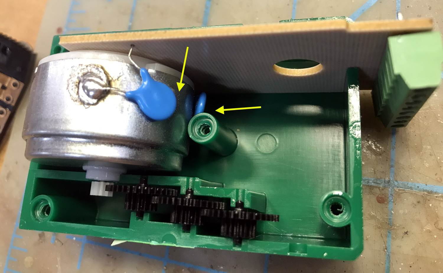


A recheck of the siding control inputs with the oscilloscope after the capacitors are installed shows a cleaner voltage with any spikes being very small.  After repeated testing, everything is working fine now.  I am now wondering if it was these voltage spikes that caused the inputs on the DS64 to fail.


Tuesday, October 24, 2023

Rebuilding Peco PL13 switch contacts

I have been working on a major side project.  I am doing an overhaul of the Ntrak club's 20 ft long staging yard.  Specifically, trying to correct the problem we have been having with getting the voltages to switch between tracks on the yellow and blue Ntrak lines.

This yard uses Peco solenoids to move the turnout points and separate solenoids with the PL13 switch contacts to route the power to each of the yard tracks.  Checking with an ohm meter these contacts were only intermittently making contact, making high resistance contact, and sometimes no contact at all.  No wonder we were having problems.


As these devices are widely used and rather expensive to replace, I thought it would be a good topic to present here what I have done to rebuild some of these that were not working correctly.

The PC board can be separated from the black plastic housing by pushing with a small flat blade screwdriver through one of the openings on either end of the housing.


Once the board was removed from the housing it could be seen that the contact areas of the board had become oxidized and worn.  Also, the two wiper parts bent at different angles, so it is likely one of them was not making good contact with the board.

I bent both contacts up at a sharper angle and tried to make that angle equal.  I also made more rounded bends at the contact areas to get smoother movement and to make more contact with the PC board.

On some of these the wire lugs that are riveted onto the board broke off with handling and others were about to so I cut them all off and soldered the wires directly onto the bord from the top side.  Any solder that came through to the bottom side needed to be filed smooth for the the board to fit correctly into the black plastic housing.  The contact pads on the board were polished with a fine steel wool.

A small amount of NO-OX is applied with a tooth pick to the contact areas of the PC board.


With the contacts and the black plastic piece in place, the PC board can be snapped into place by pressing it straight down into the housing.  Make sure the switch slides easily back and forth without catching and of course, re-test with an ohm meter.  


Friday, September 18, 2020

Sparks Yard rebuild - general update # 1

This yard rebuild project started around September 1st.  My plan is to push on with this through the fall and will be posting regular general updates along with posts on specific items as needed.  This is the first general update.

On the entry end next to the helix all 5 of the turnouts and Tortoise motors were removed.  Enough of the track and road bed was removed so a smooth transition from old and new could be achieved.   3 new Peco turnouts were assembled into a yard ladder on the bench and then installed and integrated into 4 of the existing yard tracks.  The turnout in the upper left corner will create the return loop and still needs to be installed.

At the other end (the loop end) of the yard the 5th track was realigned to be a single siding off of the return track.  In this photo the remnants of the old road bed can be seen.  The remaining 4 tracks have been cut off at this end of the yard and this yard ladder will be worked on when the entry end is finished.


Monday, November 13, 2017

Single turnout control panel

It if often said that a higher layout height gives a much more realistic view of the railroad.  While agreeing with that concept I am also aware that it makes it more difficult to see the position of the points on any turnouts compared to a layout that is lower especially if the turnout is not close the the edge of the layout.   On the Battle Mountain section of the layout I have a long siding and 4 industrial spurs for a total of 6 turnouts.   These turnouts will be controlled by push / pull rods and all are toward the back about 12 inches from the edge.  So I decided I needed some indication of the point position near the control for each turnout.

There will be 6 acrylic panels sized 1.5 x 3.75 inches.  They will be distributed along the front edge of the layout in line with their turnouts.  A paper drawing can be placed under each panel.

A 7th panel is the master for hole locations on the panels and in the front frame of the layout.

I am using a bi-color Red / Green LED connected to contacts on the slide switch that holds the points in place.  A hole was drilled in the front frame large enough for the LED to pass through. 


The panel can then be placed with the LED fitting snugly into the hole made for it in the panel.  The paper drawing is on the outside now but in the final version will be behind the panel.


This pair of photos shows both the aligned and diverging conditions on a temporarily installed control panel for testing.  Once the knob is installs it covers the larger opening made for the 1/8 inch head of the control rod.

I have since added "Pull = Diverging / Push = Aligned" or "Pull = Aligned / Push = Diverging" at the bottom as the positions can be different depending on if the turnout is right hand or left hand.
This is a diagram of how the LED is connected through the slide switch that holds the points.  The resistors are of different values as the red seemed brighter to my eye than the green with the same voltage so I gave it a larger resistor.


I am using a common anode LED.  When using a common cathode LED the voltage source polarity would be reversed.  These LED's will be powered by a 5 volt regulator circuit under the bench work which gets it's power from the 12 volt bus that runs through the layout.  The bi-color LED's are readily available on the Internet.  I get mine from www.led-switch.com.  They have a great selection of items for model railroad controls.

Monday, July 24, 2017

Catching up with some electrial projects

While finishing the helix, and the Wesso and Gloconda sections I had neglected to finish the controls for the lower or Southern Pacific staging yard.  Now with the ability to run trains around the layout that omission was really noticeable and I am  correcting it.

The yard is similar to the upper or Western Pacific staging yard but with 5 sidings instead of 4.  I am using another Digitrax DS-64 plus this little circuit I built to handle the turnout that makes the reverse loop.

This circuit uses a Set / Reset RS flip flop made from Nand logic gates to control a relay which controls the polarity of the voltage applied to the Tortoise motor.   One pole of the switches on the panel are wired a little differently so that in one direction the all send the thrown polarity and in the other they all send the aligned polarity.


Another electrical project I am working on is a power supply for the LED lighting over the Wesso section and the staging yard.  The laptop power supplies I have been using in other areas won't handle those and I have been using my bench power supply but that is needed on the bench.

Thursday, June 30, 2016

Controls for Wesso's double crossovers

Over the past couple of weeks I've been installing the turnout motors and controls.  For the interchange at Wesso there are three different possible routes.  The three drawings below illustrate the three conditions.  The SP traffic is shown in red and the WP traffic is shown in orange.

All turnouts aligned for SP westbound and WP eastbound.

East crossover diverging and west crossover aligned for westbound joint line to WP shown in orange.  SP trains hold at western approach.
West crossover diverging and east crossover aligned for SP to eastbound joint line.  WP trains to hold at western approach.

Looking at these drawings I realized that the turnouts could be operated in pairs and only require two control outputs.  I wanted to use push buttons this time and wanted an indication of which of the three conditions was active.

The control panel I came up with uses the same method used for the staging yard control panels but with simple graphics instead of a track diagram. This will have a more finished look to it once the fascia board is installed.

My push buttons are only Single Pole Single Throw (SPST) so I needed to build a small circuit for Double Pole Double Throw (DPDT) relays and for logic to control the LED's on the panel.  I used an old ribbon cable for a floppy drive to connect the board to a terminal strip which then connects to the panel.

Here's a closer view of the circuit I made and the DS64.   Only two outputs and 3 inputs of the DS64 is being used but I may use the remaining inputs and outputs to control turnouts on the eastern staging yard that will be directly above this module.

Again I am doing all the wiring before installing the module into the layout.  Here is the module laying on it's back where I can sit on a stool to comfortably do the work.  Temporary connections are made to power supplies and Loconet.

I have been marking my Tortoise motors with a "C" for closed and "T" for thrown as shown in this photo.  This helps when you can't easily see the turnouts to determine position while working on the controls.

Friday, January 30, 2015

Add a terminal strip to a Tortoise turnout motor

In the past when installing these Tortoise turnout motors, I had soldered all 8 wires to the PC board edge connector on the Tortoise then ran those to a terminal strip for later connection to the controls.  This time I wanted to simplify things a little by having a terminal strip right on the turnout motor.

The PC board that sticks out of  the bottom of the Tortoise has 8 holes that correspond with the edge connectors that are on the other side.  After measuring the spacing between the holes at about 3.8mm I found a terminal strip I could mount directly to the turnout motor.

Kobiconn P/N P02EK381V8 is an 8 position PC board mounted terminal strip with a pin spacing of 3.81mm.  I ordered mine from Mouser Electronics.  Their catalog # for this item is 158-P02EK381V8-E and they were $2.33 each.

By straightening and then re-bending every other post on the terminal strip, the post can be made to align quite nicely with the holes on the Tortoise PC board.

This photo shows how the posts will look after all of them have been re-aligned as described above.  The posts that were re-bent are the ones with the blue arrows.

After doing just one or two, I was able to do this very quickly and get them to fit perfectly in the holes.  Once soldered they were solidly mounted to the PC board.

Here is the finished installation of the terminal strip with all 8 of the post soldered to the PC board.

I am always concerned about being able to access things on the layout.  This photo shows the orientation of the turnout motor the way one is done in my previous post.  The screw heads are pointed down and the wire holes are pointed out the end.

Here's another photo showing the orientation of where the wires will connect and also the terminal strip screws when the turnout motor is mounted vertically under the layout.

Thursday, January 22, 2015

Customized turnout linkage

Over the years I've used many Tortoise turnout motors with some having served on 3 different layouts or modules. Most of these don't get installed in the conventional way, with the wire going up through the deck to the throw bar.  I often mount them upside down and use .030 diameter piano wire traveling through 1/8 inch square tube to carry the movement to turnout.  Examples of this can be seen in the recent post First trains run in staging yard.

On this most recent install on the entry end of the main staging yard I needed to mount the motor on it's side to keep clearance above and below.  I was having trouble transferring the motion correctly from the Tortoise wire to the wire connected to the throw bar.  I decided some sort of hinge was needed to connect the two.

The hinge I came up with consist of a pair of brass strips with small square brass tubing soldered along most of it's length.  The area with no tubing has a 4-40 screw and nut which creates the pivot point between the two.  The piano wires fit into the square tubes with the one from the turnout throw bar being bent at the point where it exits next to the nut.

Here is a view from underneath the layout so the placement of the L bracket and the angle that the Tortoise is attached to can bee seen.

Yesterday finished building another turnout and it seems like the best one yet.  It will be used to connect two more of the staging tracks and it's motor will be mounted in a similar way as this one.                                                                                                                  

Tuesday, December 17, 2013

Lessons learned from the old layout

In early December 2013, I dismantled the layout that I had called the California Northwestern.  I had started it almost 12 years before and it was fully completed.   It's always a bit sad to tear down a layout but at the same time I am looking forward to starting the new one.

When I built the California Northwestern my goal was to try as many new ideas (new to me anyway) as possible.  I consider this to have been a successful layout when I recall everything I've learned from it.  While I was dismantling it, I recalled many of the things I had tried, what worked well, and what did not.  I got out the camera and documented some of them.  This is how we learn and build the next layout even better than the last.

After all the buildings, trees, and other details were removed, the two sections of the layout were taken outside as it would get messy next.

I had used the Busch instant roadway product for my highway.  In this photo it is very noticeable that it had cracked and split where the material had been bent around a curve.  The material had generally degraded by about 8 years after being installed.


The raised areas of the layout were built with Styrofoam sheet to match the Woodland Scenics Styrofoam risers.  While the risers worked out fine, I would not recommend using Styrofoam for scenery base.  Besides being more messy, it also is not very firm as a sub roadbed.  The six turnouts on this layout were built on 1/8 inch acrylic sheet as a unit including the cork road bed, Peco code 55 turnouts, and Tortoise motors.  After being thoroughly tested, these units were then placed into cutouts in the foam and secured with Liquid Nails adhesive.  This meant they were non serviceable but they never gave me any problems in 11 years of service.

This photo shows one of the turnout units after it was removed from the foam.  I've really become a big fan of the Tortoise switch motors.  I've mounted them vertically, horizontally, and upside down and they've always worked.The ones on this layout had been re-used from another layout before and will be used again on the new layout along with some additional new ones.  They are about 20 years old at this point.

Here the metal shelf brackets are shown after the layout shelf had been removed.   I had set this layout just high enough at fit the file cabinet under one end. It was not until I was removing the layout that I realized that I had forgotten to put the screws into the layout shelf on last two brackets by the file cabinet.  I had never noticed any weakness there so using these type of brackets every 16 inches really works well to support a layout like this and all these will be re-used on the new layout.

Another thing I had tried on the old layout was the use of plastic paneling for the sky board and to cove the corners.  This is available in 4 x 8 ft sheets and has a textured surface.  I used it backwards as the back side is smooth.  It was attached with a few finishing nails and then painted.  This seemed to work really well.  I want to use some sort of photo backdrop on the new layout but this will give that a smooth firm surface.

With everything salvaged from the layout that could be re-used or sold, it was time to scrape off all the Styrofoam which was bagged for trash collection. The Peco code 55 track and turnout were also not re-usable. The plywood bases were then cleaned up and will be re-used.