Thursday, September 24, 2020

Updated control panel

As explained in the recent post Rebuilding of Sparks yard, a new control panel will be needed.   This is  the procedure I follow to make my control panels.

Below is a preliminary design drawn with Microsoft Visio.   Having a drawing available now would also be a good time to go over the operating scheme of this yard.  

The original momentary center off toggle switches that could route in either direction have been replaced with 6 red push button switches to select the route.  The green LED's show track selection or turnout position as they did on the old panel.  All traffic will enter through the first turnout in the closed position and pass through the yard track selected.  After going around the loop there is one more siding along the return track.  The siding turnouts are also controlled with the red push buttons. The control of that first switch is automatic using sensors just like it was before so will align itself when a train approaches to exit the yard.  The sensors can be over ridden by a pair of red push buttons.   The toggle switches will be used to control which tracks will be in use for the automatic sequencer I am planning to include using Infrared sensors.


The original control panel was made from a pattern which I kept.  This pattern was made from a scrap of hard board is seen in the photo below.  Using this ensures proper size and alignment of the mounting holes.  The new panel is made from this same pattern.

Once a design is finalized, a printout of the drawing is stuck to the acrylic sheet and taped around the edges.   After drilling, the printout is removed and the acrylic sheet is cleaned up and polished with a product that removes any small scratches.

A sheet of .030 white styrene sheet is cut to match the size of the acrylic sheet.  Using the acrylic sheet as a pattern holes are made in the styrene sheet to match the ones in the acrylic sheet. Then another copy of the drawing without the switches and LED's is used as the actual display.  Using the acrylic sheet again as a pattern two or three of the switch holes are cut out from the drawing using a hobby knife.  The drawing is then sandwiched between the acrylic and white sheets and switches are installed in these holes so that everything stays aligned and then all the other holes can be cut out.


Since this panel was made the same size as the original, it will fit right into the original housing.  Almost all of the control wiring can also be reused with a few more added.   The red and white bottle shown in this photo is the product I use to polish out any small scratches on the acrylic sheet.


Friday, September 18, 2020

Sparks Yard rebuild - general update # 1

This yard rebuild project started around September 1st.  My plan is to push on with this through the fall and will be posting regular general updates along with posts on specific items as needed.  This is the first general update.

On the entry end next to the helix all 5 of the turnouts and Tortoise motors were removed.  Enough of the track and road bed was removed so a smooth transition from old and new could be achieved.   3 new Peco turnouts were assembled into a yard ladder on the bench and then installed and integrated into 4 of the existing yard tracks.  The turnout in the upper left corner will create the return loop and still needs to be installed.

At the other end (the loop end) of the yard the 5th track was realigned to be a single siding off of the return track.  In this photo the remnants of the old road bed can be seen.  The remaining 4 tracks have been cut off at this end of the yard and this yard ladder will be worked on when the entry end is finished.


Monday, September 14, 2020

Modifying guardrails on Peco turnouts

Almost 30 years ago I attended an informal clinic during an Ntrak club meeting on modifying Peco turnouts by adding a .010 shim to the inside of each guard rail to prevent the inside wheel flanges from hitting the frog.   This method became something of a standard for the members in the group and it is something I have always done prior to installing Peco turnouts on my home layouts and Ntrak modules.   I don't add this shim to my code 55 turnouts on my Asia prototype modules as some of the equipment run on that layout has thicker flanges and the shim would make the guard rail too tight. 

This photo illustrates what happens when the space between the outer rail and guard rail is too large.  When allowed to slide inward the inner tab of the gauge can hit the frog.


These are the materials I use for this project.

Super glue, Black sharpie pen, Hobby knife with new blades, .010 styrene strips about .125 in width, several tooth picks or push pins.


The strips are cut to a length just a bit longer than the guard rails and one side is blackened with the sharpie pen.


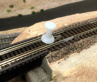
The side that is not blackened gets a fine bead of the super glue along it's length and is placed into the space between the rail and the guard rail with the glue side facing the guard rail.  Tooth picks or push pins are pushed into place to hold the strip against the guard rail while the super glue sets.


Next the excess strip is carefully cut away with a hobby knife making it flush with the guard rail.  The rails are used as a guide.  Any excess of the strip that extends beyond the guard rail is also removed.  This is where a nice new blade in the hobby knife pays off.


The shim should match the height of the guard rail and the edge is colored with the black sharpie pen.  As seen in this photo the gauge passes through without the inner tab hitting the frog.


Friday, September 4, 2020

The rebuilding of Sparks Yard

In October of 2014 construction on this layout started this layout with a double staging yard.  The first part of the staging yard was for the Southern Pacific line extending west from Weso so it is referred to as Sparks.  For those who do not know the area, Sparks is just east of Reno and SP had a large yard there which UP still uses today.

A number if issues with this yard have come up after this long and I have also learned a few things with experience of running the layout that makes me want to rebuild of the Sparks yard.  I will list those issues and planed solutions below.

  • These were my first Fast Tracks turnouts which I did with code 80 rail in a jig designed for code 55.  While the code 80 rail fit into the jig, the performance of these turnouts has never matched that of later turnouts done with code 55.  The plan will be to use code 80 Peco Electrofrog turnouts in the rebuild.

  • The layout of the yard ladders was compromised to try to fit in a 5th track.  The new layout will still have 5 tracks but with the 5th one being as a siding off of the return track.

  •  The controls were designed to allow for train movement in both directions and this added complication to the control panel and wiring.  After running the layout for 6 years and always running the trains in and out in one direction I now realize that this is not necessary.
  • A railroad herald made of Masonite that had been glued to a cabinet door above the yard fell damaging 2 control switches and cracking the acrylic of the control panel.  As the yard layout and control scheme will be different, a new control panel will be built using the existing housing.

And so it has begun as seen in the photo above.   This is the entry into the yard from the helix.  Five original turnouts have been removed and the sidings will be cut back to make way for the new track and turnouts.  Once this end of the yard is done then work will begin on the other end.  This will not be a quick project and I expect it may take a couple months as least.   The layout can still be operated using the other staging yard.  Updates will be coming in future posts.

Sunday, August 30, 2020

Freelanced steel viaduct - Part 2

This is the conclusion of a two part post on the building and installation of an over 300 foot long steel viaduct made from Micro Engineering bridge parts.  These were some the things I added to complete the steel viaduct and the surrounding area.

The code 40 rail that comes with the section of Micro Engineering flex track was used to make guard rails over the viaduct.  These were glued into place with ACC (super glue) being aligned by the small bumps that are on the ties for this purpose.  The guard rails were held in place with clamps and pins until the ACC set.
The track was hand painted with Testors rail brown acrylic paint.  The section of standard track between the viaduct and the skewed through truss bridge got ballasted with Arizona Rock and Minerals ballast.
The bridge and concrete piers got some weathering from a combination of washes and weathering powders.  I added some scribble from a dry transfer set to the bridge above one of the piers and am considering some graffiti in a few other areas but will need to find some very small graffiti decals.


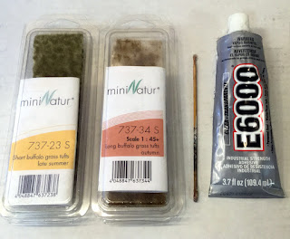
Even desert areas like central Nevada have brush and shrubs.  I use a combination of Woodland Scenics clump foliage and Scenic Express prairie grass tufts attached with a dot of E6000 adhesive on the end of a bamboo skewer.
Adding all those shrubs and prairie grass tufts may seem like a tedious task but it's actually quite enjoyable while running a train around the layout and listening to a ball game or music on the radio.
An area like this on a layout lends itself to many possible mini scenes.  Fishermen, boaters, hobos, bridge painters, and more are all things that would work here.  For now I have my canoes and some hikers admiring the bridge.

Tuesday, August 25, 2020

Freelanced steel viaduct - Part 1

I have always admired the tall steel viaducts and wanted to model one on a layout.  I don't know of one being anywhere along the line I am modeling but decided to have one anyway.   This bridge will replace a temporary "track on a stick" type bridge that I put in last March.

As there is no prototype to try to model this from it is of my own design using Micro Engineer parts.  After a lot of trial a fitting this is what I came up with.
Turns out that this viaduct did not need to be very tall so I only used the upper section of the towers and even had to carve out the area below to make those fit.
The land contours under the viaduct had to be redone after all the concrete footings and bridge piers were set in the correct places.  Those were all made from wood with joints carved into them.
Once I was satisfied with the shape of the land some basic scenery was added then the bridge was installed and the Micro Engineering bridge track with a couple of inches on each end having the bridge ties replaced with standard ties.   This track assembly was attached with E6000 adhesive.

Here is an end view looking down the line.  The guard timers have been added to the bridge ties.  Next will be adding the code 40 guard rails, ballasting the track at each end, and adding some shrubs and other details in the area under and around the bridge.

Sunday, August 9, 2020

Humboldt River rapids

In the Harney section of the layout the Humboldt River runs between the two tracks for about 4-1/2 feet.  The river is relatively straight and I felt it was not very interesting.  Also, at the end of this section near the high bridge the river bed needed to climb up about 1/2 inch.

So I recently created a little rapids area over the spot where the level changes.  I don't know if there is anything like this on the prototype Humboldt River but it seems like a fun thing to have on a layout.


Woodland Scenics water effects was used to give the water some texture in the right places and some of the ridges were highlighted with white paint applied with a toothpick.  All of the water was then given a final coat of gloss medium.

Monday, July 20, 2020

My homemade searchlight signals

My last post went through a quick review of a few ready to run and kit searchlight signals that are available and mentioned that I was going to try to make some of my own.  In this post I am going to present how I am making these.   I am using only red and green conditions for my signals.

These are the LED's I am using on my signals.  Dimensions are shown in this image that was part of the ebay listing that I purchased them from. 

These are similar in size to bright white LED's I have used in the past for locomotive lights or street lights. Small but still big enough for me to handle and solder the magnet wires to.


The wire I am using is from a roll of  wire that I have had around for years.  It measures at about .011 inches in diameter which is about 31 gauge.

This is the type of wire that is used for motor armatures, relay or solenoid coils, etc.  The darker red color is actually an insulating enamel that is very thin. so this type of wire is commonly know as magnet or enameled wire.
Surface mounted LED's and other surface mounted components come on a tracked strip like the one shown in this photo.  The individual components can easily be cut out with a hobby blade and the part drops right out.

The enamel on the wire can be scraped or filed off on the ends so that solder can stick to copper wire itself.
I am using 1/16 diameter brass tube for my pole which has a large enough interior diameter to allow for up to 5 wires of the type I am using to be threaded through without much trouble.  The target support piece was made from brass strip.  1/16 holes were drilled and the support was shaped with a dermal tool and files.
Here is the signal assembly after the magnet wires have been fed down the tube and the LED attached to the back side of the support aligned so that both red and green colors go through the hole in the support.  It is really important to have the edges of both ends of the tube filed smooth so the magnets wires won't get scraped.

Before installing the LED and wires a short section of 3/32 brass tube and a brass washer were added near the bottom setting the finished height of the signal.


A section of 1/8 inch diameter heat shrink tube is placed over the bottom end of the pole and extends past the end of the tube to create a bit of a strain relief for the delicate wires.  After shrinking the overall diameter of the bottom of the pole will be about 3/32 inches.
To make the wires easier to connect under the bench work I splice the magnet wires onto 22 to 24 gauge wires.  The splices are staggered so that only one splice at a time need to pass through the hole in the bench work.

The signal targets are 3D printed items I ordered from Shapeways.  I painted them black first then glued them to the front of the support with ACC being careful to align the hole on the target with the hole on the support and to have the shade on the target on the top.

I found it necessary to first build up the area around the back of the target with thick ACC before painting to keep the paint from creeping in between the target and the support.  After the ACC was fully dried, the entire signal was painted with Testors aluminum.

To mount these signals I drilled a 1/8 inch hole in the bench work and after feeding through the wires the pole was secured with E6000 adhesive.

These signals were connected to the same relays for the helix that control the oversized signals at the other end in the staging yards.

My signals have been in place for a few weeks now and are working great doing the job of showing occupancy on the tracks within the helix.

These signals were rather inexpensive to make, maybe 5 or 6 dollars each for materials but they are a bit of work and are not as good looking or detailed as some that can be purchased.  As I expand signaling to other areas of the layout I may also try out some of those ready to run signals.

Sunday, July 12, 2020

About N Scale searchlight signals

Signals in general and searchlight signals in particular have always been a bit of a challenge in N Scale.  In more recent times the availability of surface mounted (SMD) type of Light Emitting Diodes (LED) have improved the chances of getting something to scale.   The development of 3D printing has made it possible to include more accurate detail parts.

This prototype photo from a post on the Jersey Mikes Railroad Adventures blog shows the type of searchlight signals that would be common along the line in the era that I model and would be similar to what I would like to have on the layout.  Below is a quick overview of three brands of searchlight signals that are available.
This is an example of a N Scale searchlight signal offered by Layout Dynamics.  These are made with brass tubing for the pole that appears to be a 1/16" diameter with all of the other parts made from 3D printing.  They come fully assembled, painted, and wired with a 3 color LEDs.  They are offered in 1 or 2 head versions and with or without relay cabinets.
Some of the best to scale models I have seen are offered as kits from Showcase Miniatures.  The kit uses a 1/32" brass tube and detail parts of etched brass and white metal.  Each kit comes with 2 signal heads and can be customized by the builder.  Very tiny 3 color LED's with really fine wires can be ordered separately.
Another brand of ready to run searchlight signals is from Custom Signal Systems.  Here is a screen shot from the Corn Country Rails You tube channel that covers these signals quite well including their installation.

I decided to try making some of my own using 1/16" diameter brass tube and some 3D printed signal heads from Shapeways.  As I had already established the helix as a block on both lines and installed oversized signals in the staging yard, I installed these at the layout end of the helix.  This one is on the WP line.
Here is the signal on the SP line just before it enters the helix.  The signal to the left is from a Showcase Miniatures kit.  It is not lighted as it could not be seen anyway.  The 3D printed signal heads I am using are the same size as the ones on this kit and I am making my signals the same height as this kit is.  In a future post I will cover in more detail how I went about making, installing, and controlling my signals.


The ready to run signals are not cheap but after making a few of my own I now have an appreciation for what it takes.  My reason for making my own was not so much the cost but how delicate they looked.    I wanted to gain some experience handling and installing some of my own first and may be using some purchased ones in the future as they are more accurate and detailed than I can make.